
Use the General page of the Options dialog to define the operation of assembly modelling.
- Click File > Options > Application Options > Assembly > General.
- Use the following options to control the general operation of assembly modelling:
- Auto attachment factor — Enter the factor by which the original bounding box of the geometry of the component grows. If an attachment is outside the new bounding box, it is not included in the component definition.
|
|
|
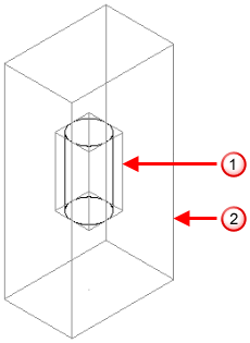
 Original bounding box of the geometry of the component definition
 Bounding box when an
Auto attachment factor of
2 is applied.
Bounding box when an
Auto attachment factor of
2 is applied.
- Show New Assembly
dialog box — Select this option to display the
Create New Assembly
dialog when you create a component and there is no current assembly. The
Create in new model option in the
Create New Assembly
dialog is disabled because you can use the solid from the current model.
Deselect this option to create the new assembly automatically with a default name. Description and Category Name are set to <none>.
- Use the solid level to create a component — Select this option to create components on the level of the source solid when creating components directly from the solid. When you modify a component, the solids of the component definition are moved onto the level of the component being modified. When converting components to solids, the solids are created on the component level.
Deselect this option to create components on the current level.
- Alter conflicting relations on general editing — Select this option to alter or remove a relationship to allow a component to be repositioned. Deselect this option to keep all the relations and restrict the new position of the secondary component.
- Show Generate Power Features dialog box — Select this option to display the
Generate Power Features dialog when you select
Generate Power Features from the source or target component context menu.
If deselected, the dialog is not displayed and the effect of selecting Generate Power Features from the component context menu is one of the following:
- If you select a target component, Generate Power Features generates Power Features for all the source components that intersect with the target.
- If you select a source component, Generate Power Features generates Power Features for all the target components that intersect with the source.
Note: This option also controls the behaviour of the Remove Features dialog. - Keep orphaned power features — When you delete a component that is the only one associated with a particular power feature, the power feature is orphaned.
Select this option to mark the orphaned power feature as out of date. The orphaned power feature is removed from the tree when you select Generate Power Features from the assembly context menu.
Deselect this option to remove the orphaned power feature from the assembly tree.
- Create local copy of component definition — This controls the setting of
Create local copy of component definition on the
Add Component dialog:
- If selected, the option on the Add Component dialog is always selected.
- If deselected, the option on the Add Component dialog is always deselected.
- Use the Text Generation from Properties section to customize the format of the text that is generated from the component definitions:
- Format of string — Enter the format of the text that is generated from the component properties. This text is used when displaying the component properties on the model. The default setting is Property Name : Value.
- Unnamed Property String — Use this option to decide the properties that have their name displayed. For each prefix in this list, the value of the property is included, but the property name is not displayed.