
Use the General Options page to specify general options about the electrode. An image of the electrode is displayed in the graphic window alongside the options.
- Enter the name of the electrode. It is also the name of the level on which the electrode is created.
- Enter the name of the group that contains the level of the electrode.
You can only enter a group name if the level is currently unnamed. The Level box displays the number of the level on which the electrode is created. If the level is currently unnamed, it is named using the string in the Name box.
- Enter a value in the Collision Gap box to specify gap between the electrode base and the active solid, to avoid collision. The electrode base is automatically trimmed back to avoid collisions:
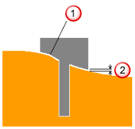
 Electrode trimmed back
 Collision gap
Note: This option is not available for electrodes created outside the Electrode Wizard.
Collision gap
Note: This option is not available for electrodes created outside the Electrode Wizard. - Click the first
 button to specify additional details to be included in the set-up sheet.
- Select an option from the Orbit Type list, to specify an orbit pattern to control the movement of the machine head during EDM. The movement takes up the difference in dimensions between the electrode, which is machined Undersize, and the actual cavity required in the workspace.
- Select Generate Fill-in to create fill-in surfaces that cover the burn regions of the electrode. The fill-in surfaces are created on a level called Electrode Fill-in Surfaces, which is in the same group as the electrode.
- Select Generate Setup Sheet to create setup sheets for the electrode. By default, two setup sheets are created:
- Machining (Electrode Detail) sheet — This sheet is created for each electrode. By default, it contains an isometric view of the electrode, which shows the electrode's dimensions. It also contains the rotation and the origin of the electrode in the bottom left corner.
- EDM (GA) sheet — This sheet contains a top view of the model and electrodes in the model. Balloons mark the origin and rotation of each electrode. This sheet is updated each time you create an electrode, and generates the setup sheet to show all the electrodes for this model.
You can change the setup sheets to suit your requirements by configuring the drawing settings.
- Click the second
button to specify which setup sheets you want to generate.
-
The Counter box specifies the counter number used in electrode names. Each electrode is named using the text in the Name and Counter boxes. You can set the counter to any integer value, or leave it empty, as long as the name string combined with the counter string is unique. If it is not, the counter is incremented automatically until the name and counter combination is unique.
If you change the name string, the counter is automatically reset to the first unique number for that name. For example, suppose you have the following electrodes in a model.
- trode1, trode2, trode3
- rib1, rib2, rib3, rib4, rib5
- extra10, extra11, extra12
If extra12 was the name of the last electrode created, the General Options page would display name as extra and the counter as 13.
If you change the name to trode, the counter changes to 4.
If you change the name to extra again, the counter reverts to 1. This is not ideal as the name of the electrodes called extra started at 10. You can change the counter to 13 (if you remember where you left off), or you can change it to a value you know you have already used. If you do the latter, an error is displayed telling you that the counter value is already in use, and the counter is automatically incremented to the next available value, in this case, 13.
- The Spark Gap value appears on the setup sheet. It is the distance required between the electrode and the product to generate a spark, and depends upon the electrode size and material, and the desired finish quality. EDM companies provide recommended spark gap values, also known as the Undersize value (see the Electrode Family page of the Electrode Wizard). This value is not used by PowerShape, but is exported to PowerMill. If it is undefined, leave the text box empty.
Other options on this page: