
Use this dialog to change the default options used to create the solid.
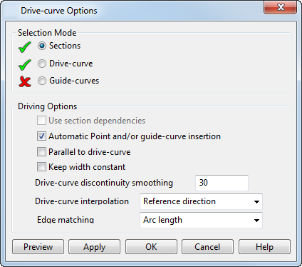
Selection mode — Select objects to define your solid. Since objects can be used for different reasons, different options are provided to reflect this. You can specify whether the objects selected are to be wireframe or a drive-curve. Select from the following:
- Sections — Select the section. You can change your selection as required.
- Drive-Curve — Select this option and select a drive curve. You can select a line, arc, curve or composite curve from your model to define the drive-curve.
- Guide-Curves — Sometimes the wrong shape is created because the wrong points on successive curves are joined. You can define the points that should be linked by creating a wireframe object between them. In the new solid, these points are joined by a smooth curve, which may not follow the shape of the wireframe object.
Note: The wireframe object which links points on laterals must cross all laterals. Also, the wireframe must already exist in your model before using this solid creation command.
To use an existing curve as a guide-curve, select this option and select the curve.
Driving Options
Automatic Point and/or guide-curve insertion — Attempt to insert guide-curves automatically. This option is available for use with separate closed curve surfaces and drive-curve surfaces with closed sections. This option is selected by default.
If selected, any previously selected guide-curve is deselected. The option is deselected if you manually select a guide-curve.
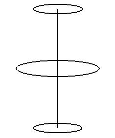
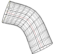
Parallel to drive curve — When a drive-curve is selected, this option is available. When selected, longitudinals leave and enter laterals with the same tangent direction as the drive-curve. For example, consider the following wireframe:
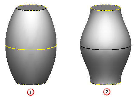
The following show the effect of deselecting
 and selecting
 Parallel to drive curve.
Keep width constant — Select this option to keep the thickness of the solid is throughout, by adding in extra points for the complex region of the drive-curve.
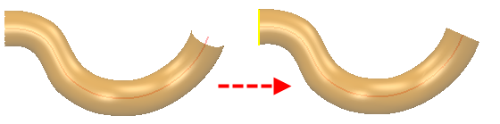
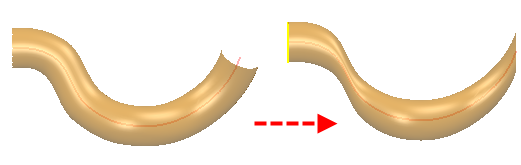
Drive Curve Discontinuity Smoothing Angle – If the angle of discontinuity is less than the value given here, all tangent discontinuities are smoothed when generating the drive-curve solid. The model below shows the result if the discontinuity of the drive-curve is greater than the Drive Curve Discontinuity Smoothing Angle.
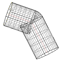
If you increase the Drive-Curve Discontinuity Smoothing Angle, the tangent discontinuities are smoothed.
Drive-Curve interpolation — This controls how laterals are orientated relative to the drive-curve.
- Reference Direction — Laterals are orientated relative to a reference direction, which is set to be approximately at right angles to the whole drive-curve. Portions of each lateral, which are at right angles to the drive-curve, are made to correspond, by linking them with longitudinals. New laterals are aligned to match the orientation. This option is best for a planar or only slightly 3D drive-curve.
- Curvature — Successive laterals are orientated so that they twist as little as possible as we move along the drive-curve. This option is best for a drive-curve that is straight or lies entirely in one plane.
- Manual Reference Direction — The reference direction is aligned with the Z axis of the active workplane without reference to the drive-curve. This option is recommended for advanced users only.
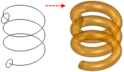
- Helical
— Use this option to create helical sweep solids. The solid below is created with
Helical Interpolation.
- Manual Alignment Direction — Aligns to, and rotates around Z-axis of active workplane.
- Minimal Lateral Variation — Minimises the changes of alignment from one lateral to the next.
Edge Matching — Select an appropriate option from the drop-down list.
Preview — Displays the solid created using the current settings in the dialog. You may continue to change the settings in the dialog until you are satisfied with the previewed solid.
Apply — Saves the solid. The dialog remains open for you to select more wireframe objects and continue creating solids.
OK — Saves the solid and closes the dialog.
Cancel — Closes the dialog and discards any changes made.