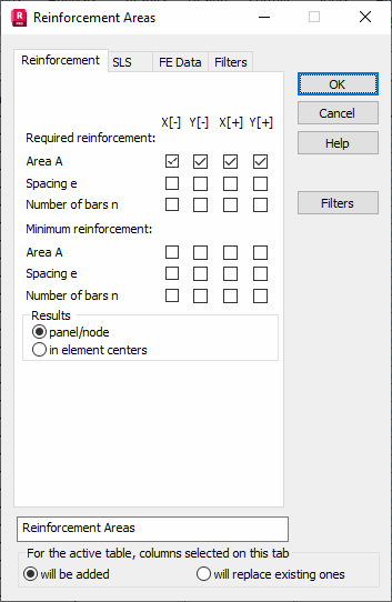
Select the Reinforcement tab in the Reinforcement Areas dialog to select quantities of slab and shell reinforcement for presentation.

The following values may be selected.
- Result type (In Element Centers and In Nodes).
- Required (theoretical) reinforcement of slabs/shells.
- Calculated reinforcement areas.
- Reinforcement spacings.
- Numbers of reinforcing bars.
- Minimum reinforcement of slabs/shells (reinforcement areas and spacings as well as a number of reinforcing bars).
Individual columns denote the following.
Y [-]: Bottom reinforcement in the Y direction
Y [+]: Top reinforcement in the Y direction
Z [-]: Bottom reinforcement in the Z direction
Z [+]: Top reinforcement in the Z direction.
The locations of bottom and top reinforcement in a panel are adopted according to the orientation of the z axis of the panel local system. This convention also holds for RC walls. For example, if the orientation of the z axis vector of the panel local coordinate system is as follows
![]() , then:
, then:
Top reinforcement:
![]()
Bottom reinforcement:
![]() .
.
See also:
