
Use the Configuration dialog to define the parameters applied during the verification of a steel member according to the Australian AS 4100 code. Open the dialog clicking the Configuration button in the Calculations dialog. The following dialog displays.
You can specify the following calculation parameters.
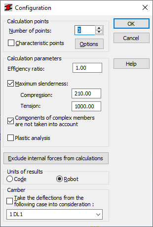
- Calculation points; you can define them 2 ways.
- By defining a number of points along the member length (the points are evenly distributed along the member length) - the Number of points option.
- By defining coordinates of characteristic points; select the Characteristic points option and click the Options button to open the Calculations in Characteristic Points dialog.
- Efficiency ratio defines the coefficient by which to multiply the plasticity limit (to increase or decrease the plasticity limit).
- Maximum slenderness; if the option is selected, the slenderness of a member is verified; in addition, you can specify allowable values of the slenderness of a member; use the Compression and Tension fields to specify the limit values; the real slenderness of a member is compared with these values (depending on the method of loading); if any of the limit values is exceeded, the member is classified as instable.
If you selected the Components of Complex Bars are not taken into account option, Robot ignores components of complex bars during calculations of these bars.
If you select the Plastic analysis option, Robot analyzes members as specified in Section 4.5 of the code. The general calculation algorithm is based on the elastic analysis; the plastic analysis is possible only in exceptional cases.
Click the Exclude internal forces from calculations button to open the Internal forces not taken into consideration dialog; this dialog box includes options that define the limit values of internal forces (thus the force values that are 'negligible' for a specific section may be disregarded). Also, you can select units for displaying results of the member design. The results are presented in the units used in the indicated steel code, or in the units used in Robot.
At the bottom of the dialog is a list for selecting a load case (dead load); the calculated displacements are treated as structure initial deflections for a selected load case. You must select the Take the deflections from the following case into consideration option then.