
Once the Reinforcement Pattern command is called up and the 'General' tab is selected, a dialog box shown below will appear on the screen.
In the above dialog box, the user may set the general parameters pertaining to the entire beam. These include:
- reinforcement segment - selection of the reinforcement generation method:
- selection of the Single Span option causes the program, to generate the reinforcement span by span
- in the case of selecting the Whole Beam option, the program selects the reinforcement in such a way so that bars be generated in one interval, i.e. that they are extended to all the beam spans.
- upper reinforcement parameters.
For upper reinforcement, the user may:
- define the placement of the bars in relation to each other, if they occur in layers of bundles (in direct contact with each other), or locate the bars to avoid their direct contact.
- define the minimal upper reinforcement diameter
- impose the tying of all main bars (the Tied All option assumes the YES value) by transversal reinforcement. The AUTO setting ties-up the longitudinal reinforcement only if the seismic dispositions have been activated or the generated reinforcement occurs in three or more layers.
- inclusion (or exclusion) of the break in concreting from the calculations.
In the lower part of the dialog box there is the Bent bars option. If the option Bent bottom bars or Bent top bars is switched on, then bent bars may be used during calculations of the beam reinforcement. Bent bars will be generated only then if a number of reinforcement layers is greater than one and at least one of the reinforcement layers ends within the span.
The following parameters of bar bends need to be determined:
- it should be selected which bars (bottom or top) should be bent
- number of bends in the plane - it specifies how many bars should be bent simultaneously in one plane
- geometrical values (spacings, angles, etc.) as shown in the drawing below.
If the Consider slab parts of T-section in quantity survey option is switched on, then the volume of concrete necessary to make a beam will be calculated for the T-section of an RC beam; if this option is switched off, the concrete volume will be calculated for the rectangular cross section of an RC beam.
If the Ignore verification of reinforcement shape during structure verification option is switched on, then the code requirements concerning diameters, stirrup shapes, bend angles, etc. will not be checked. This option is used to accelerate structure calculations.
An additional useful option in reinforcement management within the layer is Anchorage. Clicking the Anchorage button allows to open the dialog where the anchorage parameters can be defined.
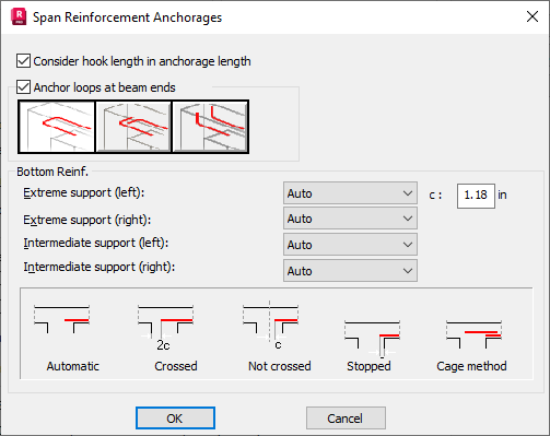
The Consider hook length in anchorage length option refers to ribbed bars (i.e. such ones for which hooks are used optionally), bent at the right angle and anchored in the support.
-
If the option is switched on, the bar anchorage length is measured from the bar end (the capacity grows from zero to the required value) considering the bend length. A bend is created if an appropriate shape of a longitudinal bar has been chosen on the Shapes tab and if it is impossible to anchor a straight bar because of too narrow support. In such a case, the length required to anchor the bar is obtained by increasing the bend length so that the total length of the hook and the straight segment ensures achieving the required capacity. If the hook length is taken into account, possible additional coefficients related to the bar end type are not considered (a bar is treated as a straight one).
-
If the option is switched off and the shape of longitudinal bars with bends is chosen, the length of a generated hook is the minimum length determined by the code requirements, while the anchorage length is measured only along the longitudinal direction of a bar. In such a case possible code coefficients related to the bar end type are considered. If length of the longitudinal bar segment in the support does not satisfy the code requirements, reinforcement will not be generated and the user will be notified about the insufficient support width.
For the Polish code PN-B-03264:2002, due to the minimum anchorage length (see point 8.1.3.4), the capacity of a bar grows according to the pattern shown in the drawing below.
 - U-shape
  - L-shape (horizontal)
  - L-shape (vertical).
Anchor reinforcement will be generated for bottom and top reinforcement (if it's necessary).
With it, the user defines the manner in which span reinforcement reaching supports must be anchored. Generation of the anchorage may be defined based on the kind of support with differentiation into edge and middle supports left and right of the span in question. The Auto option selects the bar length in the support area that meets the reinforcement anchorage conditions. The remaining three anchorage options: Crossed, Not crossed and Stopped act by forcing a cut (bar end in the support area is a value that depends on the c cover). In the case of selecting one of these three options as well as insufficient anchorage length, the program warns the user displaying an appropriate warning. The c parameter that may be defined in the top part of the Span Reinforcement Anchorages dialog box allow controlling the length of anchorages when one of the following anchorage types is selected: Crossed, Not crossed and Stopped. When the Cage method option is chosen, the reinforcement is adjusted to the successive spans in such a manner that it does not clash with the column reinforcement, and afterwards, the reinforcement is made continuous over the supports by means of additional bars.