You use the same tools and methods to draw piping in section views as in plan views. However, because you are viewing the layout from a different perspective, the results are not always what you expect. Piping drawn in a section view is drawn relative to the section view plane. When drawing in a section view, you should keep a 3D view or plan view visible to see the results of your actions. Here are some things to keep in mind:
- To establish a starting point for pipe drawn in a section view, select an existing connector. Because you cannot specify depth for the start point, you start from a connector to specify depth. If you do not connect to an existing pipe, fitting, or fixture, the depth is assumed to be zero, and the pipe is placed at the view plane and drawn relative to the section view (centered on the section view plane when viewed in a plan view). Tip: You can place the view plane for a section to specify the exact location for a pipe.
- When you connect pipe to existing pipe that is perpendicular to a section view plane (for example a pipe running north to south in a north-facing section view), the new pipe is placed according to the following conditions:
The new pipe will connect to the available connector nearest the view plane (in the foreground) for the section view. An available connector is one that is not already connected to another connector, and is within the bounds of the section view.
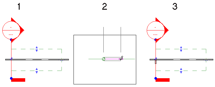
In the following example, both connectors on an existing pipe (1) are available. The horizontal segment added in the section view (2) is connected to the connector nearest the view plane, as shown in the plan view (3).
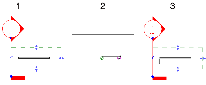
Both connectors available within the view range
-
If only one connector is available within the view range, that connector is used.
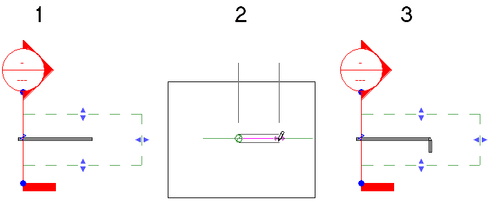
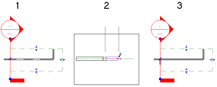
Only one connector available within the view range
Although both ends of the existing pipe fall within the view range in the following example, only one is available. The other connector is already in use. The available connector is used, even though it is furthest from the view plane.
Two connectors within the view range, but one connector already in use
If all the available connectors are outside the view range, the pipe is connected with a tee at the intersection of the view plane and the existing pipe. The centerline of the pipe is placed exactly over the view plane.
All available connectors outside the view range
If there are no available connectors within the view range, the pipe is connected with a tee at the intersection of the view plane and the existing pipe. The centerline of the pipe is placed exactly over the view plane.
The only connector within the view range already in use
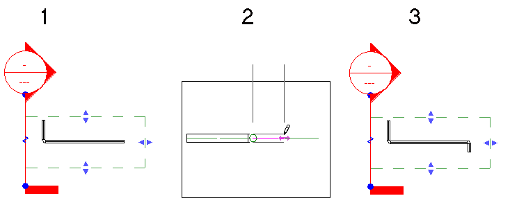
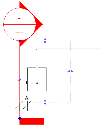
- When you draw pipe from a connector on certain family components (such as a boiler) in a section view, you should leave sufficient distance (A) between the view plane and the connector on the component to allow for the necessary segment and elbow. When there is insufficient space, the view plane is moved to allow the connection.
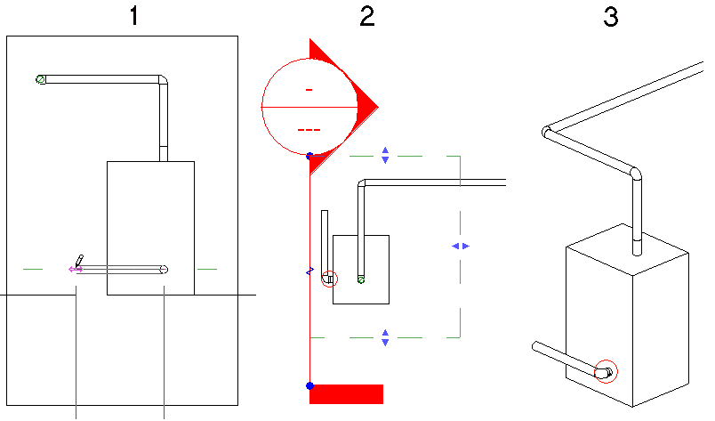
In this case, when the pipe is drawn in the section view (1), Revit adds a short pipe segment between the boiler connector and the elbow, as shown in the plan view (2) and 3D view (3).
- Pipe drawn in a section view is drawn relative to the view plane. This means that if you create a section that is not parallel to the X or Y axis in a floor plan, the pipe drawn in that section view will be placed at the same angle as the section.
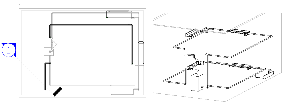
In the following sample project, you want to add piping to connect the supply main on level 2 to the circulating pump above the boiler on level 1.
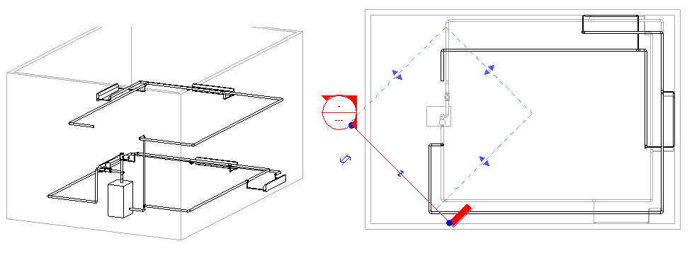
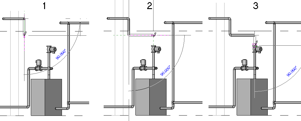
You open the section view, and use the Pipe tool to add a vertical segment from level 1 down to level 2 (1), and a horizontal segment to a point above the circulating pump (2), and a vertical segment down to the connector on the pump (3).
The connection is made, but the routing may not be what was expected. The plan view and associated 3D view show how the piping was actually created. The resulting piping was drawn with the first horizontal segment drawn parallel to the section view plane. Then, as you connected the vertical pipe to the pump, Revit added an elbow and a horizontal segment (drawn perpendicular to the section view plane) to align the final segment with the pump.