You use the same tools and methods to draw piping in elevation views as in plan views. However, because you are viewing the layout from a different perspective, the results are not always what you may expect. Piping drawn in an elevation view is drawn relative to the elevation view plane. When drawing in an elevation view, you should keep a 3D view or plan view visible to see the results of your actions. Here are some things to keep in mind:
- To establish a starting point for pipe drawn in an elevation view, select an existing connector. Because you cannot specify depth for the start point, you start from a connector to specify depth. If you do not connect to an existing pipe, fitting, or fixture, the depth is assumed to be zero, and the pipe is placed at the view plane and drawn relative to the elevation view (centered on the elevation view tag when viewed in a plan view). When you connect pipe to existing pipe that is perpendicular to an elevation view plane (for example a pipe running north to south in a north elevation view), the new pipe is placed according to the following conditions:
The new pipe will connect to the available connector nearest the view plane (in the foreground) for the elevation view. An available connector is one that is not already connected to another connector, and is within the bounds of the elevation view. (The only boundary for an elevation view is the view plane in the foreground.)
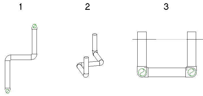
In the following example, both connectors on an existing pipe (1) are available. The horizontal segment added in the elevation view (2) is connected to the connector nearest the view plane, as shown in the plan view (3).
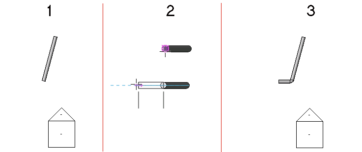
Two connectors within the view range
If there is only one available connector within the view range, that connector will be used. In the following example, the connector nearest the view plane is already used (1). When the new pipe is added in the elevation view (2), it is added at the far end of the existing pipe (3), using the only available connector.
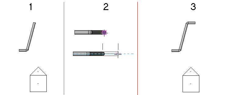
Only one available connector within the view range
If there are no available connectors within the view range, the new pipe is connected with a tee at the intersection of the elevation view plane and the existing pipe. The centerline of the pipe is placed exactly over the view plane.
- If you are connecting vertical pipe to a connector on an existing pipe that is perpendicular to the elevation view plane, the new pipe is connected to the open connector nearest the view plane (in the foreground). If there is no open connector, the new pipe is connected with a tee at the intersection of the view plane and the existing pipe.
In the following example, 2 vertical pipe segments are added to a pipe section in an elevation view. The original piping is shown in a plan view (1), in the associated 3D view (2), and in the south elevation view (3).
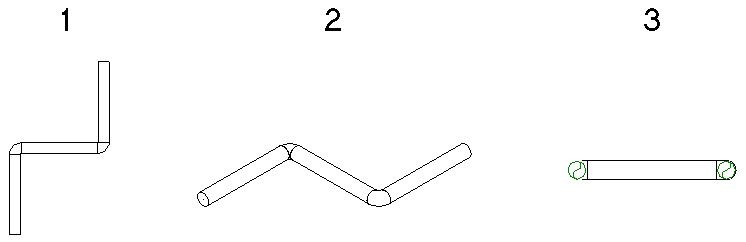
The resulting vertical segments are shown (from left to right) how they display in the plan view (1), in the associated 3D view (2), and in the south elevation view (3).
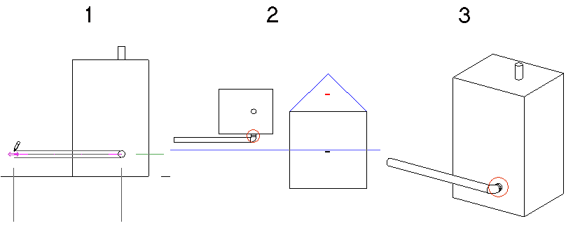
- When you draw pipe from a connector on certain family components (such as a boiler) in an elevation view, you should leave sufficient distance (A) between the view plane and the connector on the component to allow for the necessary segment and elbow. When there is insufficient space, the view plane is moved to allow the connection.
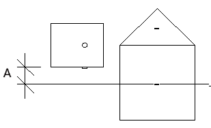
In this case, when the pipe is drawn in the south elevation view (1), Revit adds a short pipe segment between the boiler connector and the elbow, as shown in the plan view (2) and 3D view (3).