Use the same tools and methods to draw ductwork in elevation and section views as in plan views.
 Video: Display Centerlines for Round Duct
However, because you are viewing the layout from a different perspective, the results are not always as expected. Ductwork drawn in an elevation/section view is drawn relative to the elevation/section view plane. When drawing in an elevation/section view, keep a 3D view or plan view visible to view the results of your actions. Here are some things to keep in mind:
-
Revit attempts to maintain the orientation for rectangular ducts relative to a plan view. In most cases, when drawing duct in an elevation/section view, the width (W) is measured from left to right, as it appears in the view, and height (H) is measured from top to bottom. If you draw an 8" W x 12" H duct in an elevation/section view, the same duct displays as 12" W x 8" H in a plan view. This is because the perspective in a plan view sees the top of a duct and in an elevation/section view sees the side of the duct.
Note: When you press the Spacebar while adding a duct to existing ductwork, the new duct assumes the size of the existing ductwork. The Options Bar displays the width and height of the existing duct, and the duct being added is drawn with those dimensions. However, when you add a horizontal duct to an existing duct that displays as an end view (perpendicular to the view plane), the width and height are reversed. This means that the value for width is measured in the view from top to bottom, and the value for height is measured in the left to right dimension.Tip: You can click Modify | Place Duct tab
 Placement Tools panel
 Inherit Size to assume the size of the existing ductwork.
The following examples show the orientation of ductwork added in elevation/section views. In these examples, all of the existing segments are 12" W x 8" H.
In the first example, a 12" W x 8" H horizontal duct is displayed in a plan view.
In the elevation view, a horizontal duct is added to the duct. The preview of the duct shows that the orientation of the new duct has the 12" face (W) displayed as the top to bottom dimension.
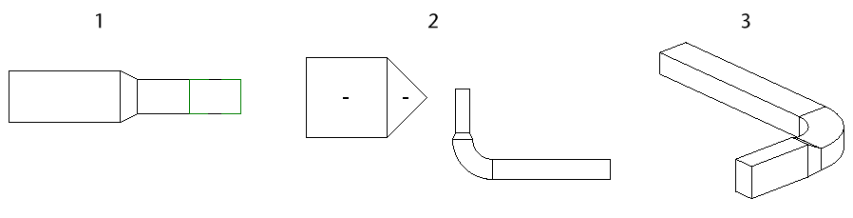
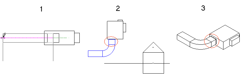
The resulting ductwork is shown below in the elevation view (1), plan view (2), and 3D view (3). The ductwork contains a transition between the elbow and the new duct segment.
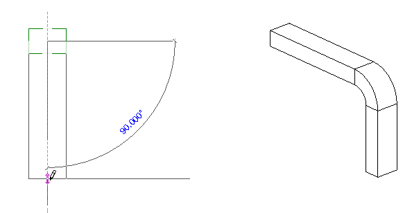
Drawing the new duct up (or down) from the duct from the previous example does not require a transition to display. The width and height display relative to the elevation view.
When connecting to an existing duct in an elevation view, it may be necessary to specify the width and height on the Options Bar to achieve the result you want.
- To establish a starting point for duct drawn in an elevation view, select an existing connector. Because you cannot specify depth for the start point, you start from a connector to specify depth. If you do not connect to an existing duct, fitting, or fixture, the depth is assumed to be zero, and the duct is placed at the view plane and drawn relative to the elevation view (centered on the elevation view tag when viewed in a plan view). When you connect duct to the end view of existing ductwork (perpendicular to an elevation view plane), for example a duct running north to south in a north elevation view, the new duct is placed according to the following conditions:
The new duct will connect to the available connector nearest the view plane (in the foreground) for the elevation view. An available connector is one that is not already connected to another connector, and is within the bounds of the elevation view. (The only boundary for an elevation view is the view plane in the foreground.)
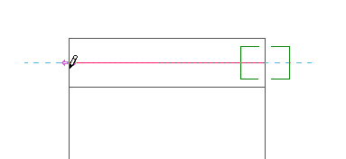
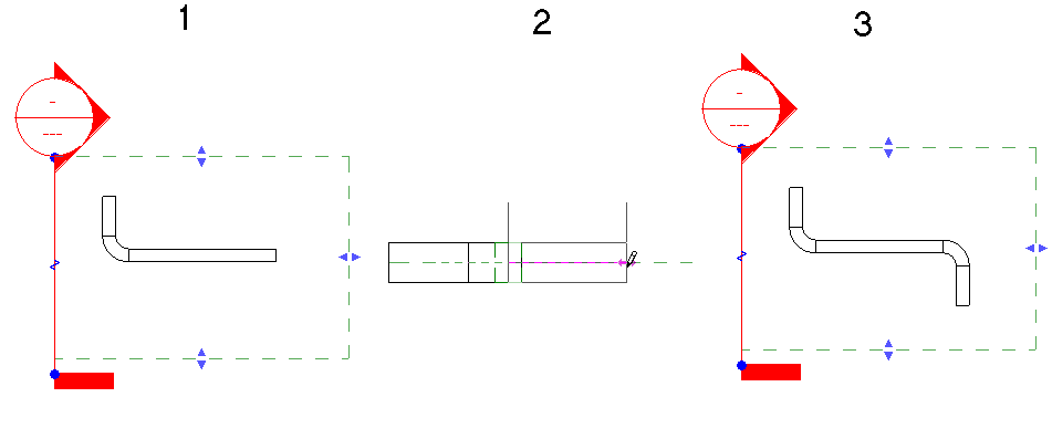
In the following example, both connectors on the existing duct (1) are available. The horizontal segment added in the elevation view (2) is connected to the connector nearest the view plane, as shown in the plan view (3).
Two connectors within the view range
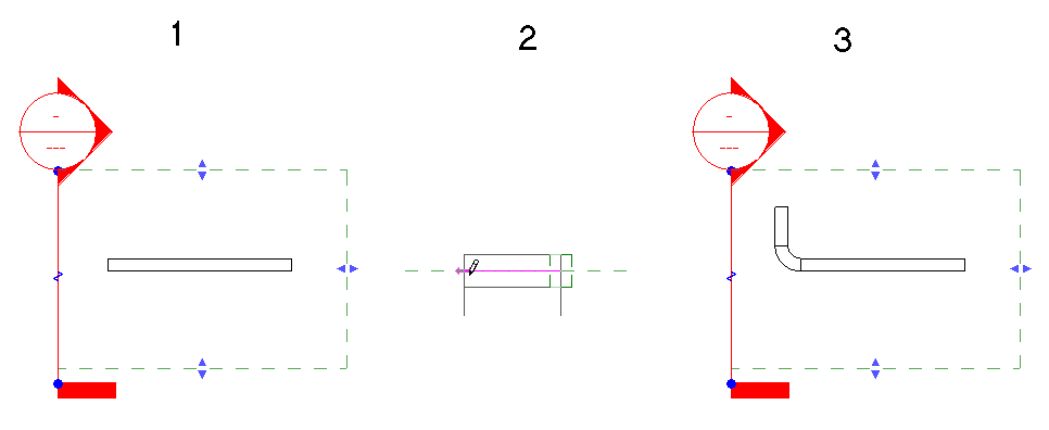
Both connectors within the view range
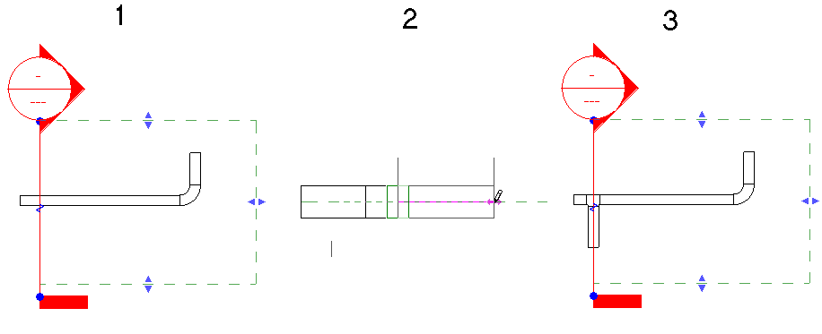
If there is only one available connector within the view range, that connection will be used. In the following example, the connector nearest the view plane is already used (1). When the new duct is added in the elevation view (2), it is added at the far end of the existing ductwork (3), using the only available connector.
Only one available connector within the view range
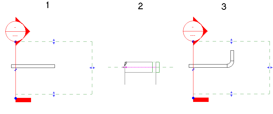
Only one connector within the view range
If there are no available connectors within the view range, the duct is connected with a tee at the intersection of the view plane and the segment. The centerline of the duct is placed exactly over the view plane.
If there are no available connectors within the view range, as in the plan view (1), the new duct (added in the elevation view (2)) is connected with a tee at the intersection of the elevation view plane and the existing ductwork (3). The centerline of the duct is placed exactly over the view plane.
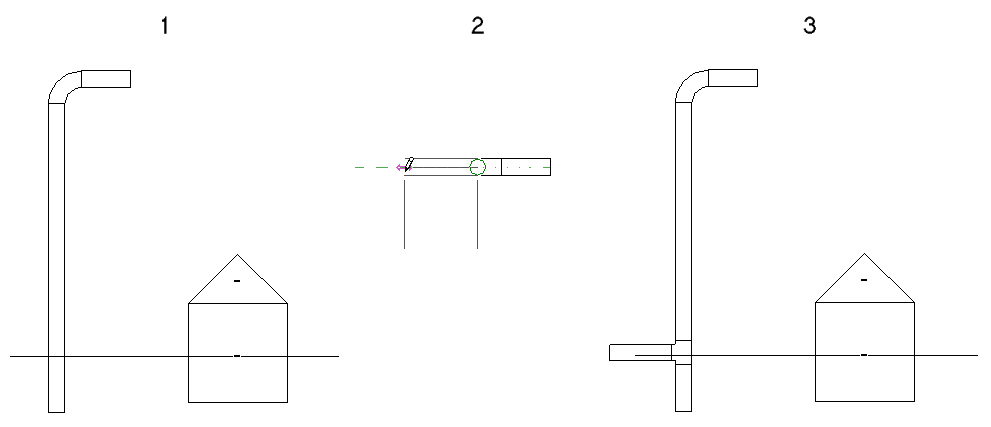
The only connector within the view range already in use
Two connectors within the view range, but one connector already in use
All available connectors outside the view range
- When you connect duct to existing ductwork that is perpendicular to a section view plane (for example a duct running north to south in a north-facing section view), the new duct is placed according to the following conditions:
The new duct connects to the available connector nearest the view plane (in the foreground) for the section view. An available connector is one that is not already connected to another connector, and is within the bounds of the section view.
In the following example, both connectors on an existing duct (1) are available. The horizontal segment added in the section view (2) is connected to the connector nearest the view plane, as shown in the plan view (3).
If only one connector is available within the view range, that connector is used.
Although both ends of the existing duct fall within the view range in the following example, only one is available. The other connector is already in use. The available connector is used, even though it is furthest from the view plane.
If all the available connectors are outside the view range, the duct is connected with a tee at the intersection of the view plane and the existing ductwork. The centerline of the duct is placed exactly over the view plane.
The only connector within the view range, but that connector is already in use
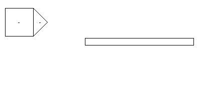
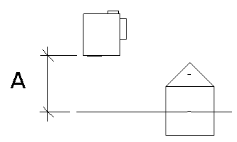
- When you draw duct from a connector on certain family components (such as a VAV) in a section view, leave sufficient distance (A) between the view plane and the connector on the component to allow for the necessary segment and elbow. When there is insufficient space, the view plane is moved to allow the connection.
In this case, when the duct is drawn in the section view (1), Revit adds a short duct segment between the VAV connector and the elbow, as shown in the plan view (2) and 3D view (3).
- If you are connecting vertical duct to an existing connector on a duct that is perpendicular to the elevation view plane, the new duct is connected to the open connector nearest the view plane (in the foreground). If there is no open connector, the new duct is connected with a tee at the intersection of the view plane and the existing ductwork.
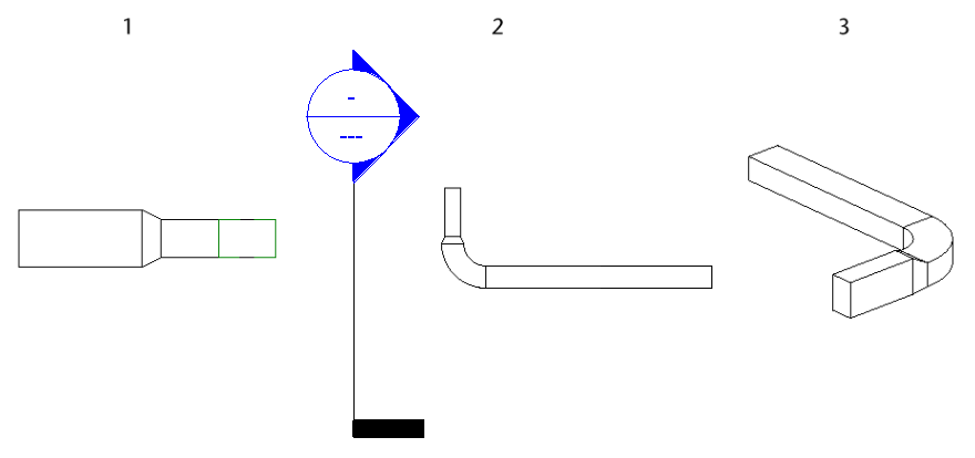
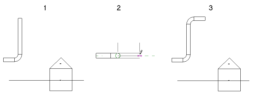
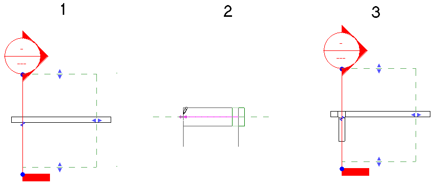
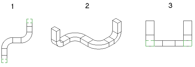
In the following example, 2 vertical duct segments are added to a ductwork in an elevation view. The original ductwork is shown in a plan view (1), in the associated 3D view (2), and in the south elevation view (3).
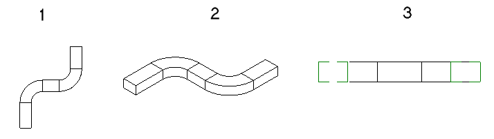
The resulting vertical segments are shown (from left to right) how they display in the plan view (1), in the associated 3D view (2), and in the south elevation view (3).
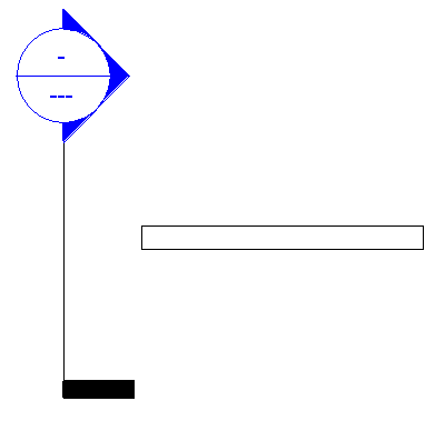
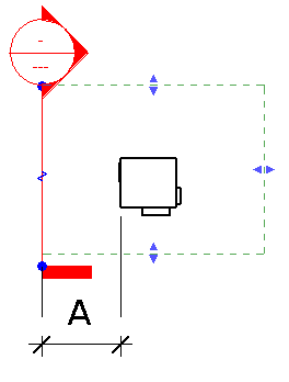
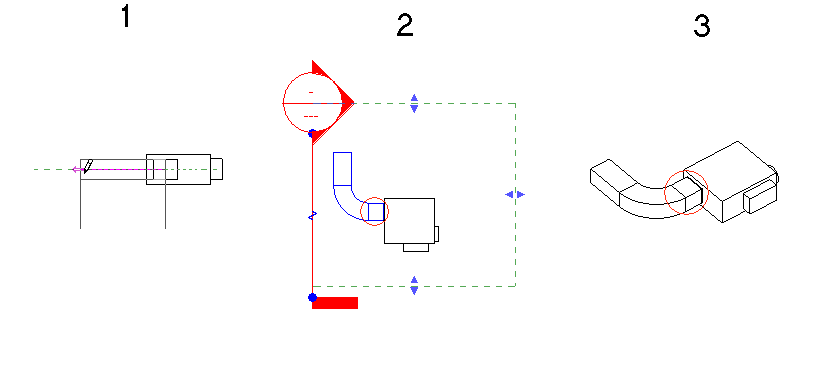
- When you draw duct from a connector on certain family components (such as a VAV) in an elevation view, you should leave sufficient distance (A) between the view plane and the connector on the component to allow for the necessary segment and elbow. When there is insufficient space, the view plane is moved to allow the connection.
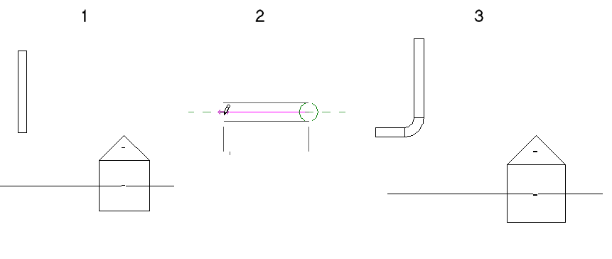
In this case, when the duct is drawn in the south elevation view (1), Revit adds a short duct segment between the VAV connector and the elbow, as shown in the plan view (2), and 3D view (3).
- Duct drawn in a section view is drawn relative to the view plane. This means that if you create a section that is not parallel to the X or Y axis in a floor plan, the duct that is drawn in that section view is placed at the same angle as the section.
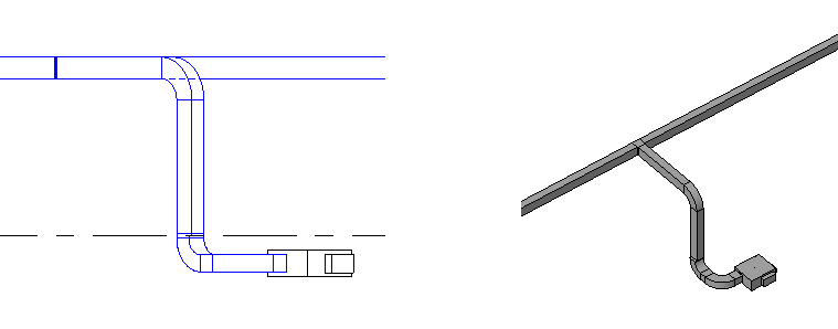
In the following sample project, you want to add ductwork to connect the segments on level 1 to the ductwork on level 2.
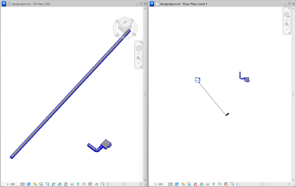
In the section view, the level 2 ductwork appears to be aligned above the level 1 ductwork. Using the duct tool, you can draw a vertical riser from the ductwork on the VAV on level 1 to the existing ductwork on level 2.
Ductwork is added from the connector on the ductwork on the level 1 VAV to the horizontal ductwork on level 2.
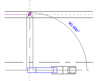
The associated 3D view shows how the ductwork is actually created. The resulting ductwork is drawn with a vertical segment and a horizontal segment to connect to the ductwork on level 2. The horizontal segment is added perpendicular to the section view plane.