
Supported Nodes
Description
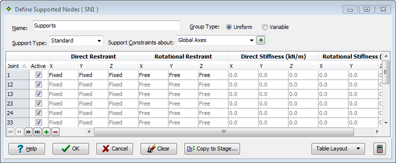
This form is used to define which nodes are supported, and the support conditions for those nodes. The supported nodes may be designated as fixed, free or sprung for any of the 6 degrees of freedom.
By default the support constraint directions correspond with the global axes directions. This may be modified for a set of supports so that the constrained direction may be about any defined orthogonal axis system.
Outline Procedure
This form may be accessed by selecting the Structure Definition Group Button in the Explorer Navigation Pane. If the required supported nodes are already defined then click on the name of the required 'Supports' Active Group Item. If no supported nodes have been defined, or if a new group of supported nodes is required, then (i) ensure that the Active Group Item is not in a Sub Model, (ii) click on the Add button on the Navigation Pane's Toolbar and (iii) select Supported Nodes from the drop-down menu.
For details of the table features, and navigation, see the help topic Table Features & Navigation.
Step 1: Selecting the supported nodes
To select the supported nodes, either click on an individual node in the graphic window with the mouse, or alternatively box around a group of nodes with the mouse. In this case, all the nodes that occur within the box will be designated as supported nodes. The current supported node (or nodes) is indicated by a red square. Other supported nodes are indicated by a small yellow square. Inactive supported nodes are indicated by a white square.
When selecting supports in the graphic window the Graphics Toolbar contains a Select menu that offers:
- All Joints - All selected nodes will become supported nodes
- Along Span End Line - Only selected nodes lying on span end lines will become supported nodes
A node can also be defined as a support non-graphically. Click on the + (Insert record) table button (or press the Insert key) and enter the joint reference number. Joint annotation in the graphics window is toggled using the 'General' toolbar.
Step 2: Defining the support conditions and local constraint directions if required
To constrain the group of supports defined in the current form in directions other than the global axes directions, select an existing non-global axes set from the drop-down menu in the field labeled 'Support Constraints About'. If none exist (apart from 'Global Axes') then click on the +(Add new defined axes set) button. The Support Local Axes form will appear on which the constraint directions for this group can be specified.
Select the 'Group Type':
- Uniform - Applies the same support conditions to every node in the group defined in the current form. Only the top row in the table may be edited.
- Variable - Allows the support condition of each node in the group to be defined independently of others.
'Stiffness' columns become editable only when the matching 'restraint' is selected to be 'Spring'.
The Table Layout button switches the location of the columns based on the upper (most significant) header being either the direction (DX, DY, etc) or condition (Restraint, stiffness, etc).
Step 3: For non-linear analysis
To define limited or lift-off supports select the appropriate support type from the field labeled 'Support Type'.
If 'Limited-Plastic' or 'Limited-Elastic' supports are selected then the table layout changes so that each limit (i.e. the load applied before the support becomes fixed or free to further loading) may be defined in the table.
The non-linear solution method applies a succession of support displacements to each limited support so as to keep the reaction within its specified limit as it performs a series of iterations. So, if limited supports (of which lift off supports are a special case) are specified and the limits are exceeded, the program automatically imposes appropriate support displacements so that the support follows the node as it moves beyond its limit.
Since the introduction of limited supports is only potentially non-linear, the program assumes that every limited support is within its specified limit during linear analysis. If any support has exceeded the specified limits, a non-linear analysis can be performed to determine the solution iteratively. The program then assumes that every limited support may exceed its limit, and therefore allows as many iterations as there are limited supports. By the time the program has found its solution, it has calculated the effects of a unit displacement at each support that has a limit.
Note that each load case for non-linear analysis must be part of a compilation.
The automatic displacements need to be kept to a minimum and this may require a number of iterations and the storage of a great number of intermediate results. At each iteration it is possible for a non-yielding support to start yielding, and vice-versa.
If multiple construction stages have been defined then supports may be made active or inactive at stages as described in Supports at Stage.
Special Mouse Actions
Supported nodes can be deleted by setting the select mode in the graphics window to 'Remove' or by using the table - (Delete record) button.
Right-clicking with the mouse in the table displays a pop-up menu offering Copy Table to Clipboard and Paste From Clipboard.
Form Graphic
Field Help
Name
The initial default name may be edited to identify this support constraints group. The name will appear for example in the Data Reports printout. In the Explorer Navigation Pane active group item description the name is prepended by a short reference acronym that is automatically generated and cannot be edited.
Group Type
Defines whether either the top row only, or all rows in the table are editable.
- Uniform - Applies the same support conditions to every node in the group defined in the current form. Only the top row in the table may be edited.
- Variable - Allows the support condition of each node in the group to be defined independently of others.
Support Type
The support may additionally be designated as:
| Type | Description |
|---|---|
| Standard | Normal linear elastic behaviour depending only on the support conditions described in the previous field. |
| Lift Off | Lift off supports are supports that can hold the structure up, but cannot hold it down. The supported node is free to move in the positive Z direction, but is restrained against movement in the negative Z direction. Lift off supports may be fixed or sprung. |
| Limited - elastic | Support limits are a more general form of lift off supports. Whilst lift off supports limit the vertical reaction at a support to a minimum value of zero, with support limits it is possible to impose maximum and / or minimum reaction limits to any of the supported degrees of freedom. Limited supports may be fixed or sprung. |
| Limited - plastic | If the limit is plastic, then each yield between iterations is assumed permanent. This would be the case if limiting friction was being modeled. Elastic limits are such that when all the load is removed from the structure it returns to its undeformed, unstressed state. (Lift off supports are elastic limited). |
For lift off supports and limited supports, an iterative non-linear analysis can be performed. The implications of this are discussed in the Supported Nodes and Non-Linear Analysis topics. To minimize run times and excessive results data, be selective in the choice of potential lift off supports or limited supports.
Support Constraints About:
The supports may be constrained about:
- Global Axes - All constraints are relative to the global axis system. This is the default condition.
- Defined Axes - The local support directions are defined by selecting this option and clicking on the adjacent button that then becomes available.
Active
A support is active at the current construction stage if the checkbox is checked. See 'Supports at Stage'.
Axial : Condition
The support constraining the 3 linear degrees of freedom may be designated as:
| Condition | Description |
|---|---|
| Fixed | No linear movement in the specified axis direction allowed. |
| Free | Not supported in the specified axis direction. |
| Spring | Supported by an elastic support in the specified axis direction. The spring stiffness is specified in the adjacent field. |
Axial : Stiffness
For a linear spring support, the stiffness is specified in this field in units of force per unit displacement. The default value of 10 to the power of 20 kN/m is effectively infinitely stiff (i.e. fixed).
Rotational : Condition
The support constraining the 3 rotational degrees of freedom may be designated as:
| Condition | Description |
|---|---|
| Fixed | No rotational movement about the specified axis allowed. |
| Free | Not supported and free to rotate about the specified axis. |
| Spring | Supported against rotation about the specified axis by an elastic support. The rotational stiffness is specified in the adjacent field. |
Rotational : Stiffness
For a rotational spring support, the stiffness is specified in this field in units of moment per unit rotation. The default value of 10 to the power of 20 kN.m/radian is effectively infinitely stiff (i.e. fixed).
Lower
The lower limit of loading, for 'Limited-Elastic' or 'Limited-plastic' beyond which the support becomes either fixed or free to further loading.
Upper
The upper limit of loading, for 'Limited-Elastic' or 'Limited-plastic' beyond which the support becomes either fixed or free to further loading.