
6.1 Line Beam Definition
Subjects Covered
- Line Beam Analysis
- Line Beam Geometry
- Drop In Span
- Parametric Shapes
Outline
It is required to form a five span line beam analysis model to represent a reinforced concrete “T” beam, with dimensions as shown below. The first span is an 8m cantilever and the third span consists of two cantilevers at each end supporting a 15m drop in span. The beam is constructed of grade C40/50 concrete (Elastic modulus 35.2205MPa)
To model the drop in span we specify the line beam to have 7 spans and specify the supports at the internal bearing locations accordingly.
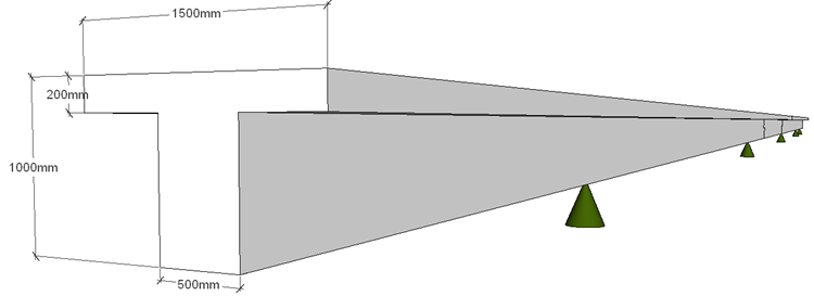
Each span is split into 1m segments which will define the results output locations.
Once the beam is defined, produce a full data summary report in PDF format and save the data file for use in another example.
Procedure
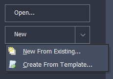
Start the program and select the New drop down button item Create From Template and pick the “EU Project” template.
Create line beam geometry
- Using the File | Titles menu option set the Project title to “5 Span Line Beam” with a sub title of “Example 6.1”.
- Also set the Job Number: to “6.1” and put your initials in the Calculations by: field.
- Close the form with ✓ OK.
- Change the navigation pane on the left hand side to Structure Definition and in the toolbar at the top of the Structure Definition pane click on Add Model | Line Beam.

The Line Beam Geometry form will open.
Set the Number of Spans: field to “7” and press the Enter key. The graphics will update to show the new configuration.
In the table, click in the Span Length field in row 1 and type in a value of “8”.
Enter appropriate span lengths in the other rows as shown in the table below.

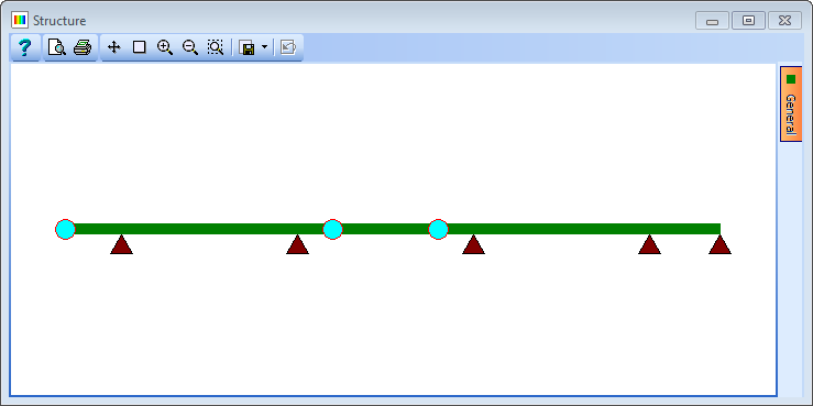
Specify the support conditions such that all span ends are fixed in displacement but free to rotate (the default), but then free the displacement at the end of the cantilever (row 1) and each end of the drop in span (rows 4 & 5). This will be shown in the graphics as:
Finally, change the value in Divide Shortest Span into: to 5, which will split the smallest span into 1m segments. The longest span is updated automatically.
Close the form using the ✓ OK button.
Define Section Properties
Change the navigation pane on the left hand side of the screen to Design Sections.

Click on the
 button at the top to display the selection list as shown and pick New Section | Parametric Shape...
In the Parametric Shape Properties form change the Shape Reference to “T” and then set height: to “1000mm”, width to “1500mm," web thickness to “500mm” and flange thickness to “200mm”.
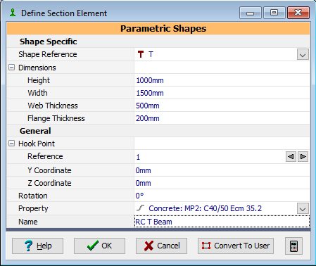
Enter a Name as “RC T Beam” and using the dropdown for Property select the grade C40/50 concrete material.
Close this form with the ✓ OK button
Change the navigation pane on the left hand side of the screen to Structure Properties then select the task option of Create Section and Beam Groups to load all defined design sections and beams into the navigation tree. In this case just the single section.

First select the Section item in the navigation window to open the Structure Properties: Section form and then to assign this property to all members in the structure draw a window round the whole structure in the Structure Graphics screen (Click at the top LH corner and release, move the cursor to the bottom RH corner and click again). The selected beams are then displayed in red.
Close the Structure Properties: Section form using the ✓ OK button.
Use the menu item File | Data Reports to open the Data Reports form.
Click the button Include All and then select the View... button to display the report. This can be viewed, converted to a pdf file and saved if required.
Use the menu item File | Save as to save the data file with a name of “My EU Example 6_1.sst”.
Close the program.
Summary
A Line Beam model is very easy to put together as the geometry is very simple. This makes it a very efficient method of analysis for preliminary design.
However, it must be remembered that a line beam only considers in plane vertical displacement and rotation about a perpendicular axis (ie. dz and ry degrees of freedom). This will of course mean that only two member actions are valid at the ends of each beam segment (ie. Moments about the horizontal axis and vertical shear).
If torsions, axial forces or transverse bending effects are significant in a structure then a line beam will not represent them.