
9.5 Offset Beams - For Finite Element Decks
Subjects Covered
- Carriageway Definition
- Setting Out Lines
- Construction Lines
- Composite Beam Structures
- FE deck with Offset Beams
- Member Eccentricities
- Dead Load Compilations
- Transfer Results to Beam Design
Outline
This example demonstrates how to model a single span bridge deck using the composite action of shell finite elements and offset beam members.

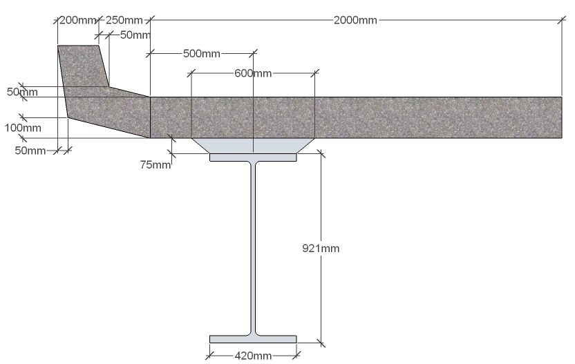
The bridge deck has a span of 21m and is constructed with four Y7 prestress beams acting compositely with a concrete slab. The deck is modelled using a finite element slab with imported prestress beams which are assigned as 'Offset Beams'. This process defines the prestress beam as a beam element with an automatically defined vertical offset relative to the deck. Upstands are added as edge beam members with an appropriate vertical offset.

The beam data for the two inner beams will be imported directly from design beam files created in example 4.3. The two outer edge beams will be created by copying an inner beam and adding an edge section with a width and depth of 200mm. The slab has a thickness of 200mm and the deck is supported on 4 discrete bearings at each end of the span.
Dead and superimposed dead loads will be applied manually. After performing an analysis of the load cases, some of the results will be transferred to one of the design beams.
Procedure
Define the Design Beams and upstand Design Section
Start the program and select the New drop down button item Create From Template and pick the “EU Project” template.
From the main menu select File | Titles and set Project Title to “Composite FE Slab and offset Beams” with a sub-title of “Example 9.5” and a Job Number “9.5”.
Add your initials in the Calculations by: field and click ✓ OK to close the form.
In the Design Beams navigation window click on the
 toolbar button to add an “Existing Design Beam” called “EU Example 4_3.sam”.
Embed this beam and rename it to “Inner Beam”.
Copy “Inner Beam” as a second design beam and rename this to “Outer Beam”.
Select Beam Definition for this beam in the navigation window and then use the Define dropdown to open the Section Definition form.
Click the table insert + button and select “In situ – regular” in the third row. This will open the Define Precast Beam Component form. The Shape Reference will be set to “Rectangle” already so enter “200mm” in both the Width and Depth fields and click ✓ OK.
Change the Y offset to “-900” and Z offset to “1470” to put the edge section in the correct location. Click ✓ OK to close both forms.


In the Design Sections navigation window click on the
toolbar button to add an “Existing Design Section...” called “Upstand.sam”.Embed this section and rename it to “Upstand”.
Creating the structure layout
Click on Add Model | Refined Model in the toolbar at the top of the Structure Definition pane.
With the "Refined Model" node selected in the Structure Definition navigation window, click on the
button and select “Design Line” from the list. This will open the Define Design Line form.Click on the green plus button at the bottom left of the form to add a new segment to the design line.
On the Define Line Segment form select the “Line” option then click on the Next > button twice.
Enter (0,0) for the coordinates of point 1 and (21,0) for the coordinates of point 2.
Click on the Next > button and then click ✓ OK to define the design line.
Click ✓ OK to close the Define Design Line form.
Click on the
button and select “Carriageway” from the drop down list to open the Define Carriageway form.Click on the Design Line field and select “DL1: Design Line” from the drop down list.
Set Carriageway Type to “Single” and enter the following coordinates in the Offset A/B fields:
(-3.8, -3), (-3, 3), (3, 3.8)

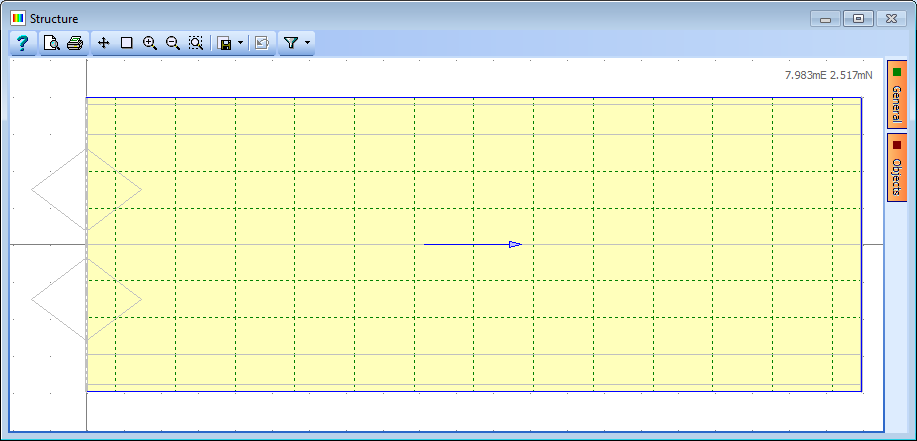
The number of notional lanes will automatically update. The notional lanes are shown in the graphics window with the traffic flow direction indicated by an arrow.
Click on each of the arrows until they are shown as double-headed. This shows that traffic can flow in either direction along each lane.
Click on the ✓ OK button to close the Define Carriageway form.
A new sub-model is added to the structure.
Click on the
toolbar button and select “2D Sub Model (GCS, Z=0)” from the drop down menu. This creates a new sub-model in the Structure Definition navigation tree.
Next we will describe the edges of the structure and lines along each abutment and pier using setting out objects and construction lines.
Select the sub-model as shown above and click on the
 button.
The menu list has changed to list objects that can be added to a sub-model.
Select “Setting Out Objects” to open the Define Setting Out Object form.
Click on the Insert Line Segment button at the bottom left of the form (this is the small + button).
Set the Type to “Line” then click on the Next > button twice.
Enter (0, 4) for the co-ordinates of point 1 and (0, 4) for point 2.
Click Next > then ✓ OK to close the Define Line Segment form.
Click ✓ OK again to close the Define Setting Out Object form.
Click on the
button again and select “Construction Lines” to open the Define Construction Lines form.On the left hand side of the form there is a list of line types.
Click on Offset parallel to DL/SOL to add a new row to the table.
Click in the DL/SOL Ref column and select “DL1: Design Line” from the drop down list.
Give the line an offset of 4m and press “Enter” on the keyboard.
Click on Offset parallel to DL/SOL again to add a new row to the table.
Click in the DL/SOL Ref column and select “DL1: Design Line” from the drop down list and give it an offset of -4m.
Click on Offset parallel to DL/SOL again to add a third row to the table then click in the DL/SOL Ref column and select “SO1: Setting Out Object” from the drop down list.
Give it an offset of 21m.
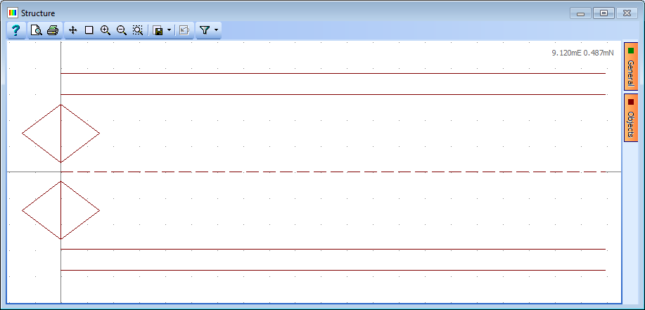
Click on the ✓ OK button to close the Define Construction Lines form.
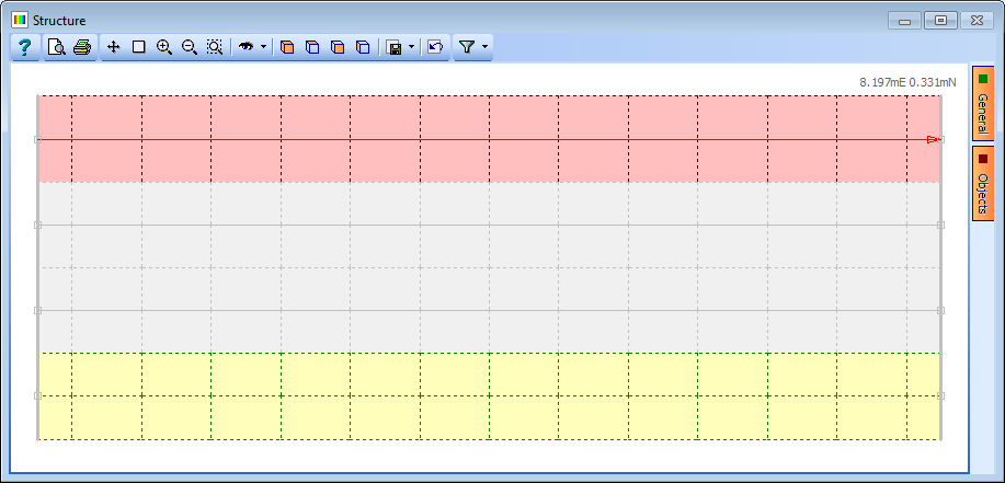
The graphics window will now show an outline of the structure as shown below:
Defining the Mesh and Supports
The next step is to define the geometry and layout of the mesh.
Click on the
button again and select “Mesh” from the drop down list. This will open the Define Mesh form.Set Member Type to “Finite Elements” and Mesh Type to “Orthogonal to span”.
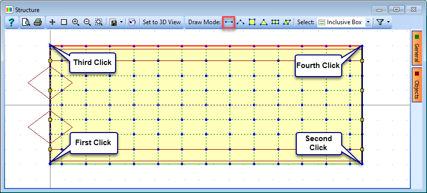
Set Longitudinal to “14” and Transverse to “8” and then click on the four edges of the deck, starting with the bottom edge. (You may need to press “Enter” on the keyboard in order for the numerical data to be input properly before clicking in the graphics window).
Change the “equal size” option for the Longitudinal elements to “set size”.
In the Set Longitudinal Size form that should now be visible set the spacing factor for the two end elements to “0.5” and click ✓ OK to close the sub-form.
Click ✓ OK to close the Define Mesh form.
The graphics will now show a plot of the mesh as shown below:
It is now necessary to define the locations of the span ends.
Click on the Refined Model node in the navigation window then click on the
button to select “Span End Lines” from the drop down list. This will open the Define Span End Lines form.
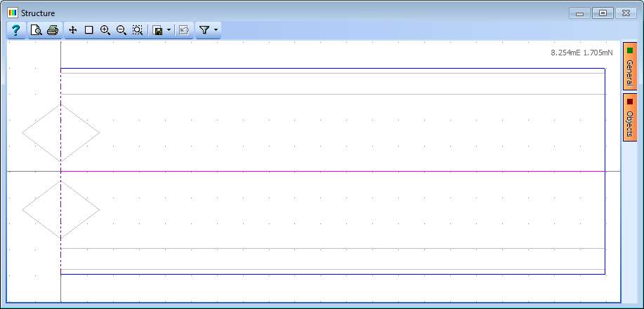
Click on the bottom left and top left corners of the left-hand abutment on the graphics window. This will draw a heavy black span end line.
Repeat this to locate the second abutment. The span end lines will be shown in the table as above and on the graphics as below:

Click on ✓ OK to close the Define Span End Lines form.
The next step will be to define the location and type of the supported nodes.
Click on the Refined Model node at the top of the navigation window and click on the
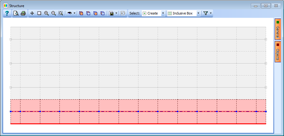
button to select “Supported Nodes” from the drop down list. This will open the Define Supported Nodes form.In the graphics window select the 8 nodes shown below:
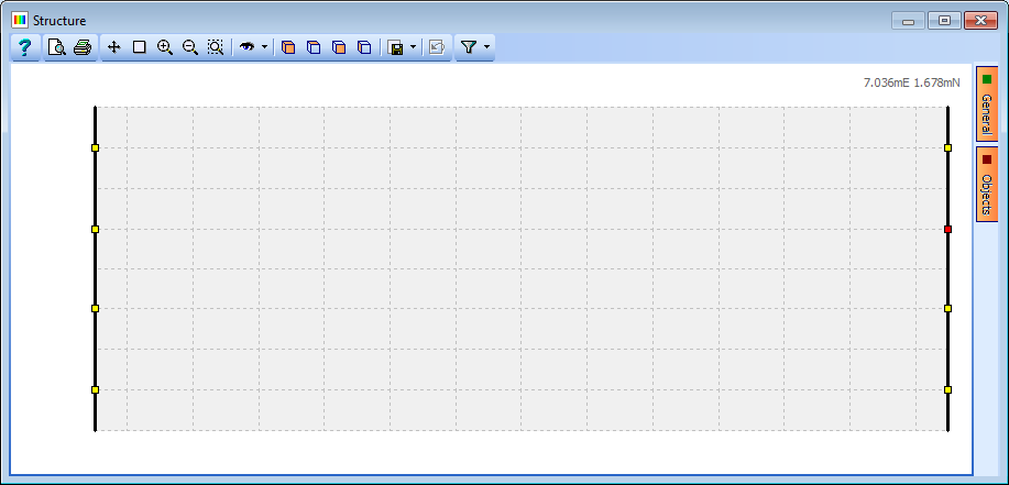
In the first row of the support table, change the support conditions so that only the DZ direction is fixed.
Change Group Type to “Variable” then click on the node just above centre of the left abutment (node 46).
Change the support conditions for this node so that it is also fixed in DX and DY.
Click on the node just above the centre of the right abutment (node 60) and change the support conditions so it is also fixed in the DY direction.
Click on ✓ OK to close the form.
Although the offset beams representing the main girders will be automatically generated when we assign the offset beams to the structure, the upstand at the edges will not be automatically created. It is therefore necessary to manually add beam members along the edges of the slab to represent the upstand.
This is done by clicking on Sub Model Members in the navigation window to open the Define Sub Model Members form, where additional members can be created.
In the graphics window click on the
 toolbar icon to draw a single member.
Click on the bottom left corner node of the mesh and then again on the bottom right node to draw one member.
Repeat this on the top edge of the mesh.
Click ✓ OK on any information form that may appear.
These members can then be split into 14 beam element segments by using the Split Beam Element... task in the Define Sub Model Members form.
In the Split Beam Elements form select the 'at nodes along element option', click on the bottom edge beam and then click on the Apply button.
Dismiss the information window and repeat for the beam on the top edge of the mesh.
Click ✓ OK to close the both the open forms.
Assigning the Offset Beam and General Section Properties
Click on the Refined Model node in the navigation window and then click on the
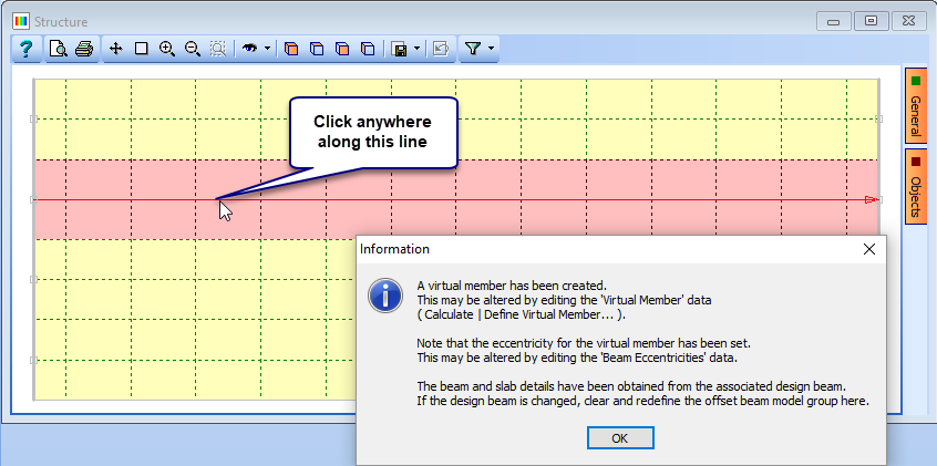
button to select “Offset Beam” from the drop down list. This will open the Define Offset Beam form.Set Beam Reference: to “Inner Beam” and Name to “Beam 2” then click on the row of joints just above the centre of the deck. It will be highlighted in red and an Information form will appear.
Click ✓ OK on the Information form and then click on the Add Additional Offset Beam... button.
For this new offset beam set Beam Reference: to “Inner Beam” and Name to “Beam 3” then click on the row of joints just below the centre of the deck where It will then be highlighted in red.
Again click on the Add Additional Offset Beam... button to create a third offset beam.
In this case use the Beam Reference dropdown to select “Outer Beam”, change the Name to “Beam 1” and then click on the row of joints one in from the top edge of the deck. The offset beam will be highlighted in red as shown below.
Once more click on the Add Additional Offset Beam... button to define a fourth offset beam.
Set the Beam Reference dropdown to “Outer Beam”, change the Name to “Beam 4” and then click on the row of joints one in from the bottom edge of the deck.
Click ✓ OK to close the form.
In the Structure Properties navigation window it can be seen that five structure properties have been automatically created and assigned, four for the precast girders and one Finite Element property for the slab. It is therefore necessary to assign a structure property for the upstand using the design section created earlier.
In the Structure Properties navigation window click on the
button to select Design Section. There is only one Design Section in the projects, which is automatically reference, so change the Section Reference Axis Relative to: field to “Origin” and then window round the whole structure.Select “No to All” in the Confirm form so that only un-assigned members are assigned this property.
Click ✓ OK to close the form.
In the main menu select File | 3D Elements View to open the 3D Elements Viewer.
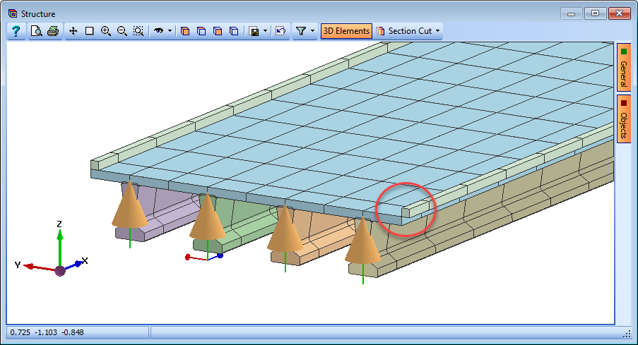
It can be clearly seen that the lateral offset of the upstand has been set in the wrong direction but this can easily be rectified by reversing the direction of the edge longitudinal beam.
In the Structure Definition navigation window select Longitudinal Beams to open the Longitudinal Beams form. The two upstand edges have not yet been created as Longitudinal beams so first window around the bottom edge and then the top edge to create them.
Select the bottom edge in the table and then use the Beam Task Reverse Order to change the direction (as seen by the arrow).
Click ✓ OK to close the form. The 3D elements view will then show the corrected location of the upstand.
When the offset beams were created the program automatically created “virtual members” that would represent the stiffness and behaviour, and contain the results of the complete composite prestressed beam. These virtual members contain a collection of finite elements and beams that make up the composite beams together with a reference axis at the centroid of the composite section.
The next step is to modify the virtual members defined for the outer beams so that they include the upstand edge members.
In the main menu select Calculate | Define Virtual Member to open the Define Virtual Member form, which already contains the four virtual members.
Change to a plan view and make sure the pick mode is set to “Beam Element”.
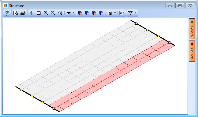
Select Offset Beam C and draw a box around the top upstand.
Repeat the process for Offset Beam D, adding the bottom upstand and then click ✓ OK to close the Define Virtual Member form.
To check that the structure has been defined correctly use the 3D Elements view by clicking on the
 icon in the main toolbar. Click on the
  icon in the graphics toolbar to activate the dynamic view function.
Defining Basic Loads
We will now apply some basic concrete dead loads for the prestress beams and edge upstand sections of our model. (Other examples in this manual, such as those in Section 10, give guidance on applying superimposed dead loads and live load optimisation).
In the Structure Loads navigation window click on the
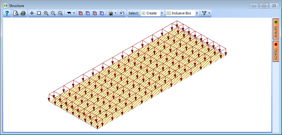
button and select Beam Member Load | Beam Element Load from the drop down list to open the Define Beam Loading form.In the first row of the table set Load Type to “F Uniform”, Direction to “Global Z”, Load Value to “Volume” and Load W1 to “25kN/m”.
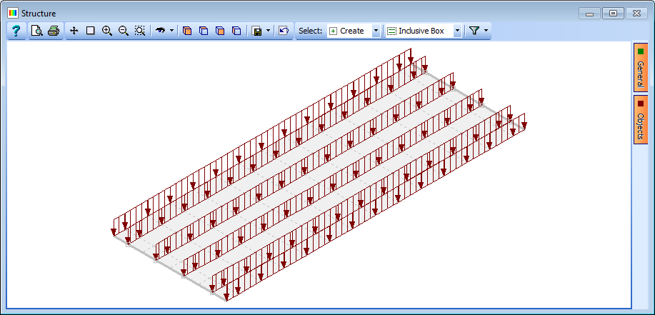
Draw a box around the entire structure to assign concrete dead loads to the prestress beams and edge upstands. (Note that because the deck is a finite element deck and the load type selected is a beam element load, loads have only been assigned to the prestress beams and edge upstands. Under different circumstances the filter tool could be used to ensure that loads are assigned only to certain members).
Change Name to “Concrete Beam Dead Load” and click on ✓ OK to close the Define Beam Loading form.

Next we will apply some concrete dead loads to the slab.
Click on the
toolbar button and select Finite Element Load | External Load.Draw a box around the entire structure.
Change the Load Type to “Force/volume”, Direction to “Global Z”, Load to “-25” and Name to “Concrete FE Dead Load”.
Click ✓ OK to close the form.
Before solving these load cases a ULS compilation of the dead loads will be created.
In the Structure Compilations navigation window click on the
button and select “Dead Loads at Stage 1”.Set the Limit State to “ULS STR/GEO” and then click twice on the + button near the bottom of the form to add 2 rows to the table.
In the first row of the table click on the Load Name column and select “L1: Concrete Beam Dead Load” from the list.
In the second row, click in the Load Name column and select “L2: Concrete FE Dead Load” from the list.
Check that the gamma values are set to 1.35 and change the Name to “DL ULS”.
Click on ✓ OK to close the Compile Loading Patterns form.
Analysis and Exporting Results
Before viewing the results and transferring them to the Design Beam Load tables it is necessary to solve the load cases.
In the main menu select Calculate | Analyse Structure to solve the load cases.

The program will open a form showing the progress of the analysis. Once the analysis has completed, click on the ✓ Done button.
In the main menu select File | Results to open the Results Viewer.
Click on the Result Type field drop down and select “Compilation”.
Click on the Result For drop down and select “Virtual Member” from the list. The Name field should show compilation C1.
Click on the Results For drop down menu on the graphics toolbar. You will see tick boxes next to each result type with Fz already ticked.
Tick the My option as well to add the bending moment diagram to the plot.
Click on the Filter toolbar button to open the Member Selection Filter form.
Click on “De-select all” then set Select by to “Virtual Member”.
Add “Offset Beam D” to the Selected Groups list and click ✓ OK to close the filter form.
Click on the
 icon to change the viewing direction.
When you have finished viewing the results click on the Member selection filter drop down and select “Select All” to remove the filter.
Select File | Close Tabular Results to close the Results Viewer.

It is required to transfer results from the analysis to the loading tables of one of the Design Beams.
In the main menu select Calculate | Transfer Results to open the Transfer Results form.
In the graphics window select the centre of the virtual beam near the bottom edge of the deck.
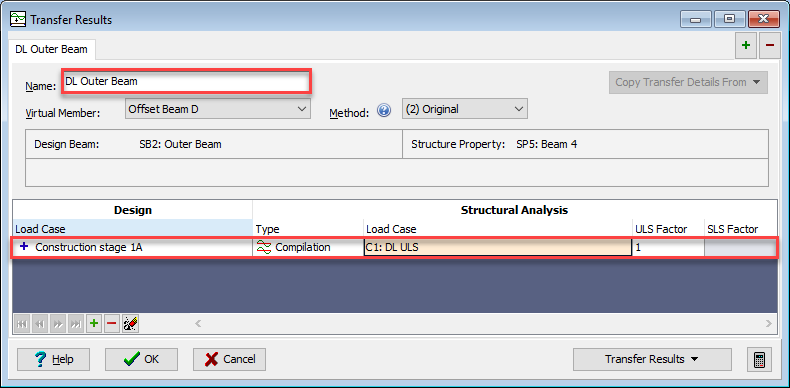
Note that “Offset Beam D” is shown in the Virtual Member field and it is highlighted in red in the graphics view.
Change Name: to “DL Outer Beam” and then click on + at the bottom of the table to add a row of data.
Click in the Design Load Case column and select “+ Construction stage 1A”.
Click in the Type column to select “Compilation” and in the Analysis Load Case column select “C1: DL ULS”. The ULS Factor will be automatically set to 1.
For this example we will set Method to “(2) Original”. The Transfer Results form will look like this:
Click on the Transfer Results button and select “Transfer Current Set to Design Beam” to transfer the results to the Design Beam load tables. Click ✓ OK to close the Transfer Results form.
In the Design Beam navigation window select SB2: Outer Beam | Beam Loads | Construction Stage 1a to examine the results just transferred.
In the main menu select File | Save as to save the data file as “My EU Example 9_5.sst”.
Summary
In this example we defined a single span structure. The slab and beam properties were derived from the design beams and assigned as 'Offset Beams'. Using this method to assign the section properties means that the properties of the slab are assigned to the FE deck and the properties of the prestress beam are assigned to beam elements which are offset vertically from the soffit of the deck.
We then applied some basic dead loads to the structure and analysed them to investigate some of the results. We then transferred the analysis results to a design beam load tables where the design of the beam could be checked following steps similar to those outlined in example 5.2 of this guide.
Note that the design beams were defined in such a way that the widths of the slabs were suitable for the widths of the finite elements in the deck to which they were assigned and the spans of the beams were defined such that they matched the span of the deck.