
Identify Model Slivers with the MAT
In the following steps we will be looking at the Model Slivers in the model. When an assembly is imported/launched into Autodesk® CFD the contact between two parts creates a single surface that the two parts share. This can cause a sliver surface to be created that was not in the initial CAD model. Unintentional surface slivers can lead to poorly formed mesh elements, or a high element count, or meshing failures. These effects can lead to longer runtimes and may be difficult to troubleshoot.
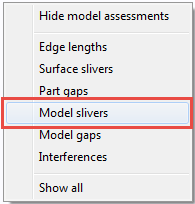
Right-click in the graphics window to bring up the context menu and select Model Slivers.
Click through the Parent Part list.
Note: By default the MAT shows us the that there is a small distance between the edges of the two parts of the housing. These two parts aren't touching so they will not create a surface sliver. This will be discussed further in the Model Gaps section.Adjust the filter to 0.03 cm by typing it in the dialog box and click Enter.
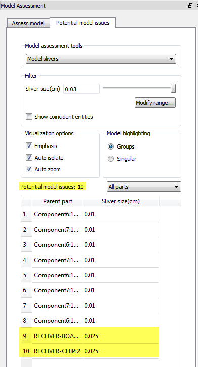 Note: There are now 10 potential model issues
Select one of the new entries from the table.
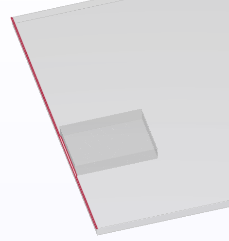 Note: The very large surface that would form the top of the board will have a very small sliver on it once imported into Autodesk® CFD.
More about Model Slivers in the Model Assessment Toolkit.