
The full parametric 3D design platform available in TruLaser makes it possible to create wireframe geometry from scratch that can be converted into laser projection data.
Step 1: Create a sketch and prepare it for laser projection
In this step, you'll create a 2D sketch in Inventor to prepare what you want to project. If you prefer, you can also use 3D modeling tools.
- Start by creating a part:
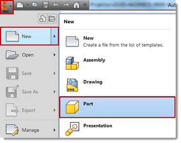
- Click
Start 2D Sketch to create all the geometries you want to project.
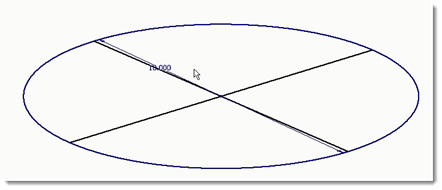
By creating a sketch, the data is now ready to convert to laser projection data.
- Click Finish Sketch.
- Save the part (.ipt) file.
Step 2: Bring the data into TruLaser
The difference between CAD and laser projection data centers around curves. Laser projectors only operate using straight lines. Any circle, spine, or arc must be tessellated into discrete straight-line segments before sending the data to a laser projector. TruLaser automatically interprets and converts curve data based on your tessellation settings in Options.
- Open a new assembly file in Inventor (select New > Assembly).
- Click Place in the ribbon and select the part file you created.
- Click the TruLaser tab.
- Click Begin TruLaser.
- Click on the assembly in the Model browser and then click
From Sketch in the TruLaser ribbon. The laser data for the assembly appears in the TruLaser browser:
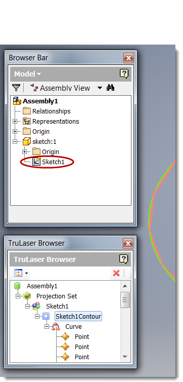
The laser projection data can now be interpreted by any brand of laser projector.
Note: If the Model browser does not appear when you open TruLaser, click the
View tab, click
User Interface in the ribbon, and then select the
Browser option.