
Sketches in Fusion
A Sketch is a geometric profile that forms the foundation of 3D geometry in a design in Fusion.
Before you can create 3D objects in your design, you first need to create the underlying sketch profiles that drive the overall shapes of the parametric solid, surface, or T-spline bodies that make up your design. Sketches are the backbone of any subsequent parametric modeling. If you create a robust sketch profile, you can improve your workflow and minimize potential downstream issues in your design.
You can create sketches on a plane or existing planar face on a body, and create geometry in relation to the XY, YZ, and ZX planes, or at any arbitrary point in 3D space.
Sketches are comprised of two-dimensional geometry like lines, circles, arcs, points, and splines. You can draw sketch geometry or project edges from existing geometry onto the sketch plane.
You can also use parameters, constraints, and dimensions to fully define sketch geometry. This ensures you can control the form of the 3D bodies you create from your sketches.
Sketch profiles
There are two types of sketch profiles in Fusion.
- An Open Profile is a series of connected 2D geometry that does not form a closed boundary.
- You can use open profiles to create surface bodies, to extrude thin solid features, or to guide some modeling operations like Loft.
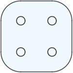
- A Closed Profile is a series of connected 2D geometry that forms a closed boundary.
- A sketch profile is shaded blue when it is closed and can be used to Extrude 3D shapes or perform 3D boolean operations like Join, Cut, and Intersect.
| Profile Type | Example | Uses | ||
|---|---|---|---|---|
| Open |  |
 |
 |
 |
| Closed |  |
 |
Unconstrained and constrained sketches
In the Sketch environment, you can create sketches that are unconstrained, partially constrained, or fully constrained.
An Unconstrained Sketch contains geometry that is still free to move in space. The sketch is not fully locked by constraints and dimensions.
- In the Browser, the icon next to the sketch indicates that it is unconstrained:
 .
. - Unconstrained sketches are useful early in the design process. Unconstrained sketches are ideal when you’re experimenting and want flexibility in your early geometric design choices. You can gradually add constraints and dimensions to a sketch as you evolve your design. However, referencing unconstrained sketch geometry in downstream design features can cause unpredictable results in complex parametric assemblies.
A Constrained Sketch contains geometry that is locked in place by constraints and dimensions.
- In the Browser, the icon next to the sketch indicates that it is fully constrained:
 .
. - Constrained sketch geometry cannot move when you try to drag it in the canvas. Constrained sketches are useful when you know the precise details of a design and are certain about your design intent. Their behavior in complex parametric designs is more predictable. However, be aware that constrained sketches can lock features in your design more robustly than you might want early in the design process. Be careful not to add too many constraints and dimensions to a sketch too early in the design process.
Types of geometry
You can create several different linetypes you can use as you create geometry in a sketch.
| Geometry Type | Description | Example |
|---|---|---|
| Sketch Geometry | The default linetype used to create geometry in a sketch. Contributes to the sketch profile. Displays as a solid blue line when unconstrained. |
 |
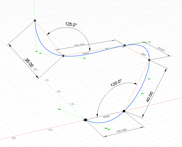
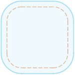
| Construction Geometry | A linetype used as a reference for sketch geometry, constraints, and dimensions. Does not contribute to the sketch profile. Displays as dashed orange geometry when unconstrained. |
 |
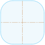
| Centerline Geometry | A linetype used to revolve sketch profiles or define symmetry. Contributes to the sketch profile. Displays as dashed orange centerline geometry when unconstrained. |
 |
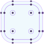
| Projection Geometry | An associative reference to profiles of 2D or 3D geometry from outside the sketch that are projected onto the sketch plane. Contributes to the sketch profile. Displays as purple geometry. Updates to reflect changes you make to referenced geometry. |
 |
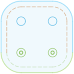
| Fixed Geometry | Any sketch, construction, or centerline geometry that you've locked in place with the Fix/Unfix constraint. Contributes to the sketch profile. Displays as green geometry. Use the Fix/Unfix constraint to unlock fixed geometry if you need to edit or move it. |
 |
| Constrained Geometry | Any geometry that is constrained or dimensioned in a way that it cannot move. Displays as black geometry. |
 |
2D and 3D sketches
A 2D sketch constrains the creation of sketch geometry to the sketch plane you select when you create the sketch:
- XY, YZ, or ZX origin planes
- Planar faces
- Construction planes
Although you can select a sketch plane anywhere in 3D space, the sketch geometry is restricted to the selected plane.
When you enable 3D Sketch, the planar restriction is removed and you can create sketch geometry at any location in 3D space.
- Use a 2D sketch to create planar sketch geometry for features like extrude and revolve.
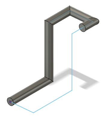
- Use 3D Sketch to create paths for tubing, sweeps, and lofts, or to create surface edges.
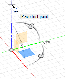
3D Sketch Manipulator
The 3D Sketch Manipulator lets you control where you create sketch geometry in 3D space. It is common to all 3D enabled sketch tools.
The 3D Sketch Manipulator is comprised of 3 components:
| Manipulator Component | Use |
|---|---|
| Plane | Acts as a temporary sketch plane. |
| Axis | Lets you create orthogonal sketch geometry in all directions. |
| Rotation Handle | Lets you rotate the sketch plane to a specific angle or reset to the default orientation. |
You can leverage each of these components to build sketch geometry in 3D space.
Sketch contextual tab
When you create a new sketch ![]() or edit an existing sketch, the Sketch contextual tab displays alongside the other toolbar tabs on the toolbar.
or edit an existing sketch, the Sketch contextual tab displays alongside the other toolbar tabs on the toolbar.
The Sketch contextual tab contains tools that let you create, modify, and constrain 2D and 3D sketches that drive the 3D geometry of a design.

You can still access the other visible toolbar tabs like Solid and Surface while you're editing an active sketch, in order to use tools like Extrude. However, when you invoke a 3D modeling tool while you're editing an active sketch, the sketch is finished automatically and the Sketch tab disappears.
Sketch Palette dialog
When you create a new sketch ![]() or edit an existing sketch, the Sketch Palette dialog displays in the canvas.
or edit an existing sketch, the Sketch Palette dialog displays in the canvas.
You can control the following options in the Sketch Palette dialog:
- Contextual Options: Displays options specific to the active sketch tool or selected geometry.
- Linetype: Converts selected sketch geometry to a different linetype.
- Construction: Creates construction geometry that you can reference without contributing to the boundaries of sketch profiles.
- Centerline: Creates centerline geometry. Centerlines contribute to the boundaries of sketch profiles.
- Look At: Rotates the camera to look directly at the active sketch plane.
- Sketch Grid: Shows or hides the sketch grid in the canvas.
- Snap: Enables or disables the ability to snap to the sketch grid.
- Slice: Temporarily cuts through bodies where they intersect with the active sketch plane.
- Show Profile: Shows or hides blue shading for closed sketch profiles.
- Show Points: Shows or hides sketch points.
- Show Dimensions: Shows or hides sketch dimensions.
- Show Constraints: Shows or hides sketch constraints.
- Show Projected Geometries: Shows or hides projected geometry in the active sketch.
- 3D Sketch: Enables or disables the ability to sketch in 3D.