
Activity 6: Flat areas
In this activity, we will use the Horizontal strategy to mill all the flat areas on the part,inside the machining boundary.
Prerequisites
- Activity 5 is complete.
Steps
Start a new 3D Horizontal operation and verify that Tool #14 - Ø5 mm R0.5 bullnose, is still the active tool.
- On the Manufacture toolbar, Milling tab, select 3D > Horizontal
 .
. - Select the Tool tab

- Be sure tool #14 - Ø5 mm R0.5 bullnose is still the active tool.
- On the Manufacture toolbar, Milling tab, select 3D > Horizontal
Limit the toolpath area to cut below the Top.
- Click the Heights tab
 .
. - The Top height drop-down list should be set to Model Top.
- Set the Top height Offset to -1 mm. Since we Face milled the top, this area is already machined. The Offset insures the toolpaths will start below the top face of the part.
- Click the Heights tab
Depth cut settings, Optimal load and Stock to leave.
- Click the Passes tab
 .
. - Enable the Multiple Depths.
- Set Maxiumum Stepdown to .4 mm.
- Set Number of Stepdowns to 3 mm.
- Click the Passes tab
Controlling the rapid retract clearance method and the ramp type.
- Click the Linking tab
 .
. - Set the Retraction Policy drop-down list to Minimum retraction.
- Set the Ramp Type to Plunge.
- Click OK to start the calculation.
- Click the Linking tab
Activity 6 summary
In this activity you selected a 3D Horizontal operation, restricted the top of the machining area, set multiple passes to remove material on all the flat areas, except the Model Top.
| The calculated toolpath is shown below. | The simulated toolpath is shown below. |
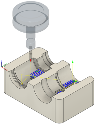 |
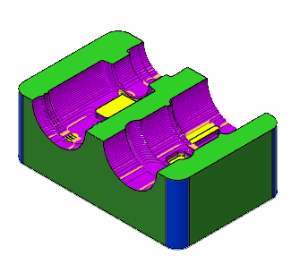 |
The toolpath is shown with a red arrow start, yellow rapid move, green lead in/out move, blue cutting moves and a green arrow at the end.