
Rigid body connector
A rigid body connector ties together the translational degrees of freedom of multiple bodies. The rigid body connector constraint is available for the following simulation analyses:
 Static stress
 Modal Frequencies
 Structural bucklling
 Nonlinear static stress
 Quasi-static Event simulation
 Dynamic Event simulation
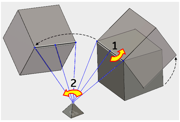
Consider the following illustration. The cube is able to rotate about the edge where the rigid connector is attached (shown as "1" in the image) . Also, the rigid connector and the cube can rotate freely about the anchor point at the tip of the pyramid (shown as "2" in the image). The vertices and edges of both solid bodies are incapable of preventing rotational movement. In fact, the tip of the pyramid acts like a ball-joint, allowing rotation of the connector and attached body in any direction.
To prevent this motion using only rigid connectors, three rigid body connectors are required:
- One connector between an anchor point on the pyramid and at least three non-collinear points, two edges, or a face on the cube
- One connector between a different vertex on the pyramid and a point, edge, or face on the cube
- One connector between a third vertex on the pyramid and a point, edge, or face on the cube. The three anchor points cannot be collinear, or they form a hinge.
Alternatively, you could also attach the second or third rigid connector anchor points to vertices on separate solid bodies, as long as the three anchor points are not collinear.