Defines the fold or refold features that you apply to a sheet metal part.
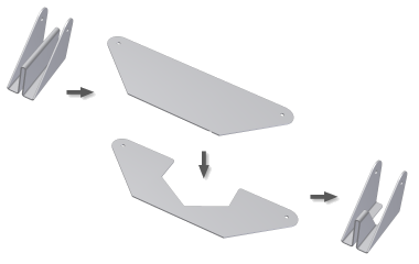
The contents of the dialog boxes for the Unfold and Refold workflows are the same.
- Access
- On the ribbon, click Sheet Metal tab
 Modify panel
  Unfold or Refold
- Unfold or Refold Reference (A)
 Specifies the face or reference plane to use as the reference to which bends or rolls are unfolded or refolded. This reference is labeled A in the illustration to the right. When you enter the workflow, this command is active by default.
 - Unfold or Refold Geometry (B)
 Specifies individual bend or roll features to unfold or refold. Available selections are labeled B in the illustration.
  Specifies all bend or roll features to unfold or refold. Available selections are labeled B in the illustration.
 - Sketches (C)
 Specifies unconsumed sketches to unfold or refold. Available selections are labeled C in the illustration. Available only after you select unfold or refold geometry.
 Parent is visible Select to see both the original (folded position) sketch and the unfolded copy of the sketch. When sketches unfold, a copy of the sketch is created, and displays on the flattened face. The original sketch (or parent) remains in the folded position.
- Dialog box image panel
- Displays an image that changes, depending on the available geometry.
- Unfold - Flat faces present
-
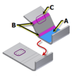
- Unfold - No flat faces
-
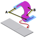
- Refold - Flat faces present
-
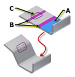
- Refold - No flat faces
-
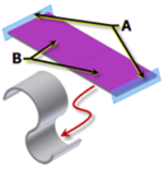
- Unfold - Contour roll
-
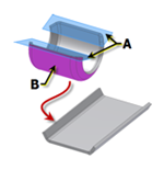
- Refold - Contour roll
-
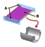
- Enable/disable feature preview

- Controls display of the preview of the fold or unfold result.