Using this option, you can define / modify symbols of axes, levels, and sections used in elements of an RC structure.
To begin defining styles, open the Styles of symbols dialog from:
- Menu Formwork Drawings > Styles > Styles - graphic symbols
- Ribbon: ASD - Drawings > Settings > Styles > Styles - graphic symbols
- Command line: RBCT_DEF_SYMBOL_STYLE.
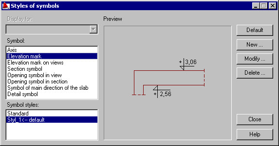
Under Symbol, there are several types available:
- Axis
- Elevation mark
- Elevation mark in views
- Section symbol
- Opening symbol in view
- Opening symbol in section
- Symbol of main direction of the slab
- Detail symbol.
For every symbol type, a standard style has been defined. After highlighting a symbol type and a symbol style, a preview displays.
Use the buttons on the right to work with symbols:
- Default - click this to restore a default (standard) symbol of an axis, level, or section.
- New - click this to open a dialog (Axis , Section symbol, Opening symbol in view, Opening symbol in cross-section, Symbol of main direction of the slab, Detail symbol or Elevation marks on plans/Elevation mark) where you can define a new style of the selected symbol type (based on the existing style).
- Modify - click this to open a dialog ( Axis , Section symbol, Opening symbol in view, Opening symbol in cross-section or Elevation marks on plans/Elevation mark) where you can modify a selected symbol type.
- Delete - click this to delete a highlighted symbol style.