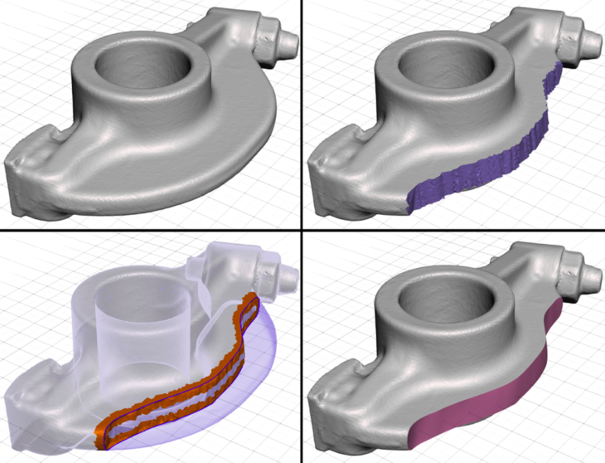
The Smooth Boundary Tool provides a way to deal with the irregularity of mesh surfaces. When you paint a triangle selection on an unstructured mesh, you will inevitably end up with at best a jagged approximation of the shape you are imagining, as in the image below-left. By smoothing this rough boundary, we can create a nice, crisp edge loop embedded in the mesh. In addition, Smooth Boundary creates face groups, which are useful in many other Meshmixer tools.
The hotkey for the Smooth Boundary tool is b.
The property panel for Smooth Boundary is shown below. These parameters are described in detail in the sections below.
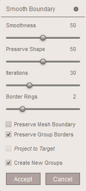
Smooth Boundary also has some useful functionality that is not reflected in the property panel. See the Pins section below for information on how to constrain the shape of the smoothed boundary curve.
How it Works
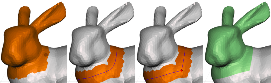
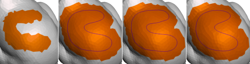
When you run Smooth Boundary on an input selection, you will notice that the selection highlight changes from the area you have selected to a strip around the border of the selection. Only this area is modified. A useful way to understand what happens is to drag the Smoothness slider to 0. If you do this as in the second image below, you will see that the mesh is identical to the input mesh. As you drag the slider up, the boundary of your input selection slides along the surface of the mesh, so that the edge loop becomes smoother. This boundary is highlighted in blue. The neighbouring vertices fully contained inside the orange region are also repositioned to some extent, to try to improve triangle quality.
One property of Smooth Boundary is that the mesh connectivity is not modified. The vertices are constrained to slide on the input surface, so the shape of your object does not change in most cases, although small/sharp features may be modified. This is not always desirable, as low-quality triangles and even inverted faces can be created by Smooth Boundary, which need to be resolved by Remeshing. See the Pins section below for an example of this.
Smoothness, Preserve Shape, and Iterations
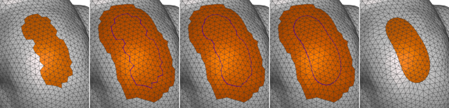
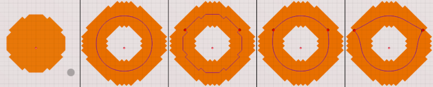
The main control over the smoothness of the curve is the Smoothness slider. In the image below, we show the initial selection, the default Smoothness, then Smoothness of 25 and 100.
The parameters Preserve Shape and Iterations also affect the smoothing. It is somewhat difficult to explain the effect these have. The smoothing is iterative, so Iterations is the number of rounds. More iterations means a smoother result. Preserve Shape controls a per-iteration modification that counteracts the smoothing to some extent, in an attempt to preserve overall shape. You can play with this slider to see its effect. Preserve Shape can also reduce local foldovers in some cases.
Border Rings
As mentioned above, when we smooth the boundary loop, we also smooth vertices in the neighbourhood of this embedded edge loop. The neighbourhood is defined as a number of rings of triangles, specified with the Border Rings slider. The default is usually fine, but if you have local foldovers, you can sometimes resolve them by increasing this. Also, if you are smoothing multiple borders simultaneously, we cannot apply the operation if their neighbourhoods overlap. So, you can reduce Border Rings to remove this overlap, as shown in the image below.
Preserve Mesh Boundary
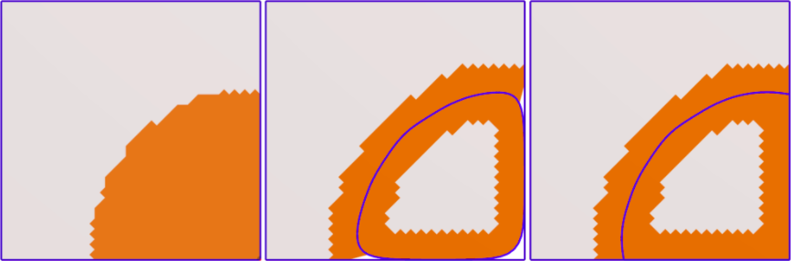
Normally if your input selection contains a portion of the mesh boundary (see image below, left), it will be smoothed just like the interior boundary loop (middle). The Preserve Mesh Boundary option pins boundary vertices in place, so that they cannot be modified (right).
Preserve Group Borders
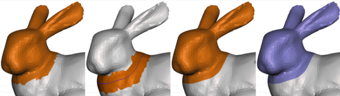
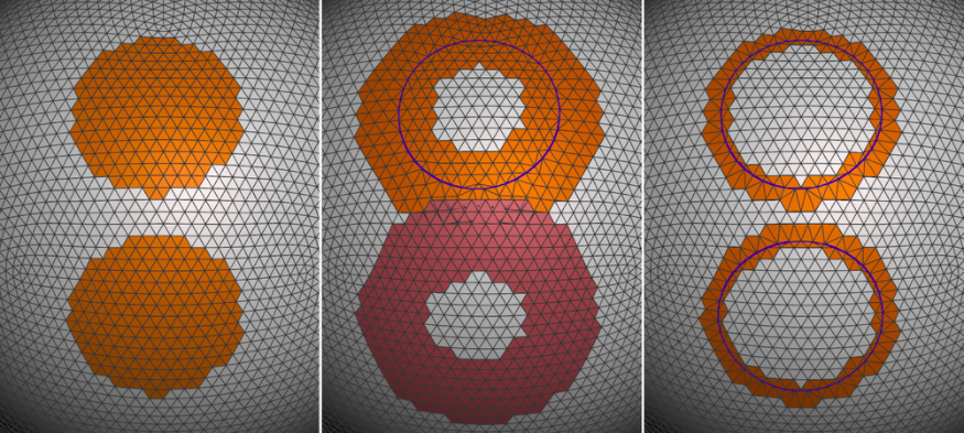
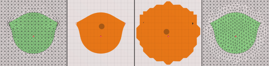
Smooth Boundary tries to not modify the shape of your existing face group borders. So, we constrain vertices on face group boundaries to only slide along their respective boundary edge loops. This works in most cases, but it will prevent you from smoothing an entire face group's border, as shown in the second image below. Un-checking Preserve Group Borders disables this constraint, so that you can create a smoothed version of a face group, as shown in the two right images.
Project to Target
The Project to Target checkbox is only available if a Target object (see 3D Scene) is currently active. In this case, the smoothed boundary loop of your selection will be re-projected onto the target object rather than the input surface. A common use for this capability is if you want to clean up the modified areas of a shape, perhaps produced by something like a topology optimization algorithm, or by manually cutting away regions. In the example below we have cut off a portion of the shape (top right). If we set the original shape as target, and then Smooth Boundary on the blue region with Project to Target (and Preserve Groups disabled), we can smooth the boundary on the input shape. This creates a much cleaner border for the blue region. We have then used the Deform > Smooth tool to polish the region interior.
This Project to Target functionality also works when the target object is a different shape than the input. We have not found many places where that seemed like a good idea, but perhaps you will!
Pins
By default, Smooth Boundary creates a smooth version of your input selection boundary. However, in some cases you might wish for some local non-smoothness, such as on corners. Also, in some cases it may be useful to be able to only smooth a portion of the boundary loop. You can do this with Pins.
The Pins functionality is similar to some other tools like Deform > Warp. You can left-double-click on vertices of the blue boundary loop to add pin constraints. Note that currently you should set Smoothness to 0 before you add the pins; otherwise, they may end up at the wrong vertices (we are hit-testing against the un-smoothed mesh). In the middle image below, we have added two pins, which are displayed as red spheres. I can then increase Smoothness and the pinned vertices will maintain their position, creating two corners in the smoothed boundary.
You can also left-click-drag to tweak the position of the pins. In the right-most image above, I have moved the pins outward. However, the further you move the pins, the more likely it is that you will create local foldovers. The left-most image below shows that after I accepted the above operation, the mesh had foldovers around the pins. To resolve this, I select the face group (using the double-click shortcut) and then expand the selection a few times using the > hotkey. The selection must contain the foldovers entirely. Then a quick Edit > Remesh cleans up these issues.
If you don't want to remesh the entire facegroup interior, after you >-expand once, you can Ctrl-left-double-click on the face group again to de-select, then >-expand a few more times. This way, you select only a strip around the border. This is a useful sequence that you may find yourself using frequently when working with Smooth Boundary.
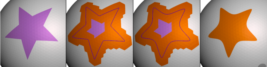
The images below show another example where we have created a region with a sharp corner. Combined with tools like Edit > Extrude and Edit > Offset, constrained Smooth Boundary is very useful if you are creating things like armor panels for 3D characters.