A view dimension style contains the dimension types created by the selected view. Each view can be dimensioned differently.
The list of dimension types is located on the View dimension tab and you can access it:
- From the tree panel, by selecting the View dimension branch.
or
- From the View definition tab, in the View dimension area, by clicking
 (Set).
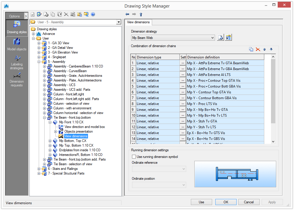
All dimension chains that are created by the selected view are listed in the table. Running dimension settings can be customized along with the settings for the dimension chains.
Set a dimension strategy
- Select a predefined dimension strategy from the list. The existing strategies can be renamed and further definitions can be added.
| Button | Function |
|---|---|
|
|
Define a new dimension strategy. A copy of the current settings is created and a new item appears in the drop-down list. |
|
|
Rename a dimension strategy. The current settings are saved under a different name. |
Modify a dimension strategy
The set of dimension chains is modified using the four buttons on the right side of the Combination of dimension chains area.
| Button | Function |
|---|---|
|
|
Add a new dimension chain. |
|
|
Delete a dimension chain. |
Add a new dimension chain
A new dimension chain is created from an existing dimension chain
- Select a dimension chain to use as a template.
- Click
 (Add).
The new dimension chain is added to the list and can be modified.
Delete a dimension chain
- Select a dimension chain to delete.
- Click
 (Delete) to delete the dimension chain from the table.
Change the order of the list
The order of the dimension chain list can be modified with the two arrow buttons,
![]() and
and
![]() .
.
Modify a dimension chain
The Combination of dimension chains area displays all the dimensions chains created by the selected view.
A dimension chain is modified directly in the table by selecting the dimension type and the dimension definition from the list.
Only definitions that have been created by Advance in the Dimension request category can be selected. The dimension definition settings are accessible by double-clicking a row in the table. Their properties are configured as described in Dimension Request.
All the views containing the modified dimension chain are also changed.
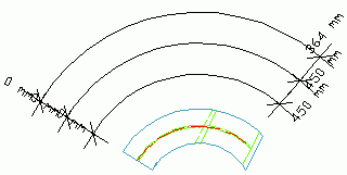
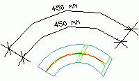
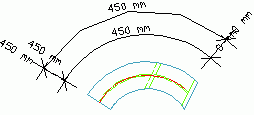
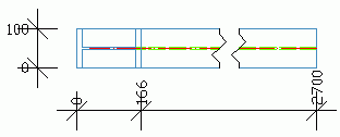
For dimension type, the following options are available:
| Dimension type | Example |
|---|---|
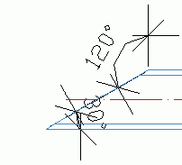
| Angle |
|
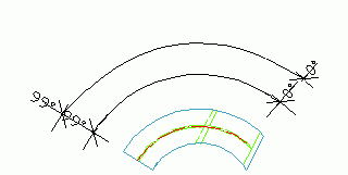
| Arc angle, absolute |
|
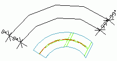
| Arc angle, absolute from end |
|
| Arc angle, relative |
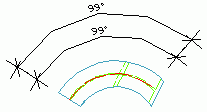
|
| Arc angle, relative and absolute |
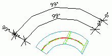
|
| Arc angle, relative and absolute from end |
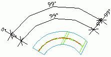
|
| Arc length, absolute |
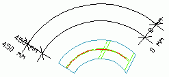
|
| Arc length, absolute from end |
|
| Arc length, relative |
|
| Arc length, relative and absolute |
|
| Linear, absolute |
|
| Linear, relative |

|
| Linear, relative and absolute |
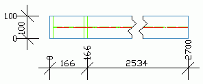
|
| Linear, relative and absolute from end |
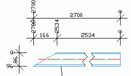
|
| Radial |
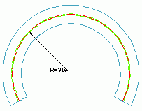
|
| Slope triangle |

|
| Slope triangle, horizontal |

Displays the slope relative to the X direction. |
| Slope triangle, longest edge |

Displays the slope relative to the longest side of the triangle. |
| Slope triangle, smallest edge |

Displays the slope relative to the smallest side of the triangle. |
| Slope triangle, vertical |

Displays the slope versus Y direction. |
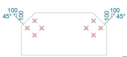
- Click
 .
.
- Combine equal distances using Group equal distances.
| Equal distances not grouped |
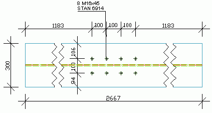
|
| Equal distances grouped |
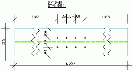
|
For a linear absolute dimension type, two more options are available:
- Broken dimension line - this option is not available for any relative dimension type.
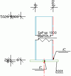
- Co-directional running dimension text - allows setting the position of the dimension text.
| Option | Result |
|---|---|

|

|

|

|

|

|
Customize the running dimension settings
- Check Use running dimension symbol.
Setting the ordinate reference and position defines the symbol placement.
| Ordinate reference | |
|---|---|
| Left side of the main assembly. |

|
| Left side of the total assembly. |

|
| Right side of the main assembly. |

|
| Right side of the total assembly. |

|
| Ordinate position | Description |
|---|---|
| Above | The symbol is placed above. |
| Below | The symbol is placed below. |