Creates or edits a format file (.set) for a report. A format file defines the fields to include in the report, the field order, table options, and more.
FindCommand entry: AEFORMATFILE
List of Options
The following options are displayed.
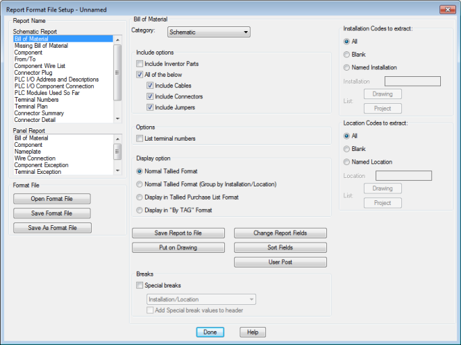
Report Name
Specifies which report to run.
Format File
- Open Format File
- Browses to a format file to open and edit.
- Save Format File
- Saves a format file to use when running a single report or a group of reports with Automatic Reports.
- Save As Format File
- Saves a format file with a different name.
The default location for format files is \Users\{username}\AppData\Roaming\Autodesk\AutoCAD Electrical {version}\{release}\{country code}\Support\User\.
Category
By default, the report extracts schematic components. Select a different Category to run the report for one-line, one-line bus-tap, hydraulic, pneumatic, P&ID, or user-defined components. These components are each identified by a unique WDTYPE attribute value.
Installation Codes to Extract
Filters the information extracted for the report based on installation values.
- All
- Extracts all components regardless of installation value.
- Blank
- Extracts only those components that do not have an installation value.
- Named Installation
- Extracts only those components that have an installation value matching the value entered in the box. Wild-card characters are supported.
-
Drawing. Select one or more installation values from a list of values used on the active drawing.
Note: If the Bill of Materials option Include Inventor Parts is checked, Drawing is disabled.
- Project. Select one or more installation values from a list of values used across the project.
-
Drawing. Select one or more installation values from a list of values used on the active drawing.
Location Codes to Extract
Filters the information extracted for the report based on location values.
- All
- Extracts all components regardless of location value.
- Blank
- Extracts only those components that do not have a location value.
- Named Location
- Extracts only those components that have a location value matching the value entered in the box. Wild-card characters are supported.
-
Drawing. Select one or more location values from a list of values used on the active drawing.
Note: If the Bill of Materials option Include Inventor Parts is checked, Drawing is disabled.
- Project. Select one or more location values from a list of values used across the project.
-
Drawing. Select one or more location values from a list of values used on the active drawing.
Save Report to File
Opens a dialog box where you can define the settings used when you save a report to a file. Settings include:
- File types
- Whether to include title lines, time, date, column labels, and more
- Whether to show the included lines on the first section only when a report contains multiple sections
Change Report Fields
Opens a dialog box where you can:
- Specify the fields to include in the report selecting from a list of available fields
- Specify the field order
- Define the field labels
- Define the field justification
Put on Drawing
Opens a dialog box where you can specify settings used when inserting the report as a table. Settings include:
- Table style
- Column width
- Title
- Layer
- Section definition and placement
Sort Fields
Opens a dialog box where you can select the fields to use when sorting the report data.
User Post
Opens a dialog box where you specify which custom user-defined options to run when the report is generated.
Breaks
- Special Breaks
- Sorts and breaks the report into sections based on the selected values. The drop-down list displays the special breaks allowed for the report.
- Add Special Break Values to Header
- Adds the special break value to the page header. For example, if you select a special break of Installation/Location, the installation and location values for the section are displayed in the section header.
Bill of Material Report Only
Include Options
- Include Inventor Parts
- If your project is linked to an Inventor assembly, this check box is enabled. Specifies to include the electrical parts from the linked Inventor assembly in the report. Linked devices that are represented in both an AutoCAD Electrical toolset drawing and the Inventor assembly are not duplicated in the report.
- All of the Below
- Specifies to include cable, connector, and jumper information in the report. Use the individual check boxes to include or exclude any of these.
Options
- List Terminal Numbers
- Lists each individual terminal in the format strip-ID:terminal number. Otherwise terminals from the same strip are combined into a single entry with a quantity.
- Full (Panel Bill of Material Only)
- Specifies to include all schematic component information not found on any panel layouts in the report.
Display Option
- Normal Tallied Format
- Combines and tallies components that have the same catalog information. Subassembly items and multiple catalog values are reported as line items directly following the main catalog item.
- Normal Tallied Format (Group by Installation/Location)
- Combines and tallies components that have the same catalog, installation, and location values. Subassembly items and multiple catalog values are reported as line items directly following the main catalog item.
- Display in Tallied Purchase List Format
- Each catalog value is reported and tallied as a single line item. Subassembly items and multiple catalog values are reported as separate line items.
- Display in By TAG Format
- All instances of a given component tag or terminal tag are reported as a single line item.
Missing Bill of Material Report Only
Options
- Include Components
- Specifies to include schematic components.
- Include Cable Markers
- Specifies to include cable information in the report.
- Include Connectors
- Specifies to include connector information in the report.
- Include Terminals
- Specifies to include schematic terminal information in the report.
Schematic Component Report Only
Options
- Include Components
- Specifies to include schematic component information in the report.
- Include Cable Markers
- Specifies to include cable information in the report.
- Include Connectors
- Specifies to include connector information in the report.
- Include Children for Above
- Specifies to include child symbol information in the report.
Component Wire List Report Only
Options
- Include Stand-alone Terminals
- Specifies to include terminal information in the report.
- Include Plug-jack Connectors
- Specifies to include connector information in the report.
Wire Label Report Only
Report Filter
- Display Wire Label
- Display the report in a wire label format.
- Display Cable Label
- Display the report in a cable label format.
Change Report Fields
- Wire Label
- Opens a dialog box where you can define the fields, field order, and characters between fields for the wire labels.
- Cable Label
- Opens a dialog box where you can define the fields, field order, and characters between fields for the cable labels.
Label Quantity per Connection
Specifies the quantity of wire labels or cable labels. Wire labels are generated for every wire connection while cable labels are generated once for every cable.
Number of Columns to Display
Arranges the labels in the specified number of columns.
Horizontal/Vertical Arrangement
Arranges the labels horizontally or vertically across the columns.
Panel Component Report Only
Options
- Include Nameplates
- Specifies to include nameplate information in the report.
- Include Terminals
- Specifies to include terminal information in the report.
Skip Components With
- Blank Device Tag Values
- Specifies to exclude any panel footprint without a tag value.
- Blank Manufacturer/Catalog Values
- Specifies to exclude any panel footprint without a catalog assigned.
Panel Component and Terminal Exception Reports Only
Conditions for Report
- Panel Item not on Schematics
- Lists the panel terminals that do not have related schematic terminals.
- Schematic Item not on Panels
- Lists the schematic terminals that do not have related panel terminals.
- Multiple Instances
- Lists the panel terminals that appear to be duplicates.
- Mismatch between Schematic and Panel
- Lists the data mismatches between the panel and schematic representations of a terminal.