Climb mill — Select this option to have the tool on the left side of the machined edge (in the direction of tool travel). Disable it for conventional milling, with the tool on the right side of the machined edge.
Bi-directional rough — Enable this option to mill in both directions. If disabled, conventional roughing happens and the cutting path moves in one direction with rapid, above-stock return movements to set up for the next pass. Climb mill controls the cutting direction.
Use finish tool — If disabled, the same tool is used for both the Rough and Finish passes. Enable Use finish tool to create a new tool for finishing. This finishing tool is identical to the tool that was selected for roughing. The name of the new tool is appended with -finish. For example if the roughing tool is named endmill1.0, the finishing tool is called endmill1.0-finish. This finishing tool is not permanently assigned to a tool crib, it is a temporary tool for use in the current document only.
Finish cutter comp — Enable this option to use cutter compensation for the Finish and Semi-finish passes of a milled feature.
Rough cutter comp — Select this option to enable cutter compensation for the rough pass of all milled features in the current document by default. See Finish cutter comp for more information.
Chamfer cutter comp — Select this option to enable cutter compensation for chamfer operations of all milled features in the current document by default.
Partline program — This is a particular kind of cutter compensation for milled features. If enabled, the drawing dimensions of the feature are output as the toolpath instead of the center line of the tool. The tool selected to cut the feature is still important even when using part line programming. If the same tool is used for roughing, be sure that the actual tool diameter does not deviate too far from the diameter of the tool used by FeatureCAM to ensure proper area coverage for the roughing passes. Also ensure that the diameter of the selected finishing tool is small enough to cut your entire feature. If you have selected a tool too large to fit into a tight corner, you cannot correct the toolpath with just cutter compensation.
FeatureCAM automatically calculates the entrance point of your finish pass and adds a linear move and a ramping move (based on the Ramp diameter attribute) to your finish pass to accommodate cutter compensation. If you receive a warning in the operations list such as "Can't find ramp in/out arc" or "Can't extend end of open profile" then correct the problem by decreasing the Ramp diameter attribute or changing the Pre-drill point.
Minimize tool retract — Enable this option to reduce the amount of retracting that the tool does while milling a feature. Instead of retracting, the tool continues feeding to its next location.
Individual rough levels — The rough pass is often performed at multiple Z levels due to the depth of the feature. Enable this option to list them all so that you can edit the attributes of each level separately.
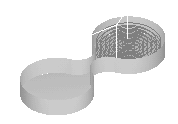
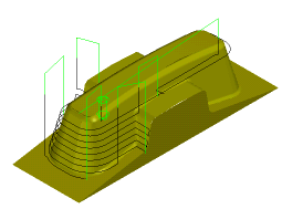
Depth first — Enable this option to cut each region of a feature completely before moving on to another region. The toolpaths descend in Z.
If this option is deselected then all regions of a feature are cut at one Z level before descending to a deeper Z-level.
The images below show how regions of a feature are completely cut before moving on to another region.
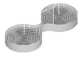
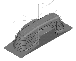
If you are using Multiple roughing tools or Multiple finishing tools, to efficiently rough out tight corners, Depth first is also useful.
The images below show a tool finishing tight corners in a depth first manner.
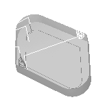
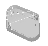
Reorder — The Reorder attribute tells FeatureCAM to re-sequence the toolpaths to minimize retractions while trying to avoid full width cuts. Use Reorder when you have a part where several separate regions are cut. If you want the toolpaths to move directly across a surface without worrying about retractions, deselect Reorder.
For Z-level operations (rough or finish), the Reorder attribute enables zone machining, where the toolpaths descend in the Z (or -Z) direction if that is more efficient than cutting the entire part in complete Z levels. The phone handset example below shows that the toolpaths cut the top of the part in complete Z levels and then cut one side and the other.
5-axis position menu — There is often an alternate orientation option for accessing a face. Select from:
- Standard — The default orientation.
- Alternate — The alternative orientation to the default.
- Use Post Preference — Uses the position (Positive or Negative) set in XBUILD in the Five Axis dialog for the Preferred orientation of the primary rotary axis option.
- Use Axis Limits — Allow FeatureCAM to select the orientation that best fits within the axis limits set in the MD file.
Clamp avoidance — Click this button to display the Clamp Avoidance dialog where you can specify the options for avoiding clamp solids in 3 axis and NT toolpaths.
Non-Cutting Moves — Click this button to display the Vortex Non-Cutting Moves dialog where you can specify whether to retract and increase the feed rate on non-cutting moves for vortex toolpaths.
Use new ID/OD groove toolpath — Select this option to use the new Side Groove toolpath style, or deselect it to enable backwards compatibility. When this option is selected, these changes are made to side groove toolpaths:
- The plunge and retract moves are checked for gouges.
You can disable the gouge checking on plunge and retract moves by deselecting the Plunge gouge check option on the Strategy tab of the Feature Properties dialog.
- You can use wind fan finishing for the finish operation.
To specify the wind fan settings, click Wind Fan on the Strategy tab of the Feature Properties dialog, and use the Wind Fan Finish Options dialog.
- You can use arc lead-in moves for the finish operations. Otherwise you can only use a linear lead-in move.
To use an arc lead-in move, select Arc Lead on the Stepovers tab of the Feature Properties dialog.
- You can set a start point for the finish pass.
To set a start point, use the Start point attribute on the Plunge tab of the Feature Properties dialog.
Trochoidal slotting
Trochoidal cut — Enable this option to use a trochoidal cut on a Simple Groove. Select the direction of the trochoids for a trochoidal cut, from CW (clockwise) or CCW (counter-clockwise).
Instead of a simple slotting cut, the tool uses a series of circles, for example:
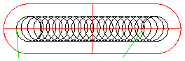
A trochoidal toolpath reduces the load on the tool.
Max tool diameter % — This is the percentage of the groove width that is used to determine the diameter of the tool that will be selected.
Max step distance % — This is specified as a percentage of the tool diameter and represents the maximum distance between neighboring circles of the toolpath.