You can use the Turning tab of the Turning Feature Properties dialog to edit the machining setting of a Turning feature.
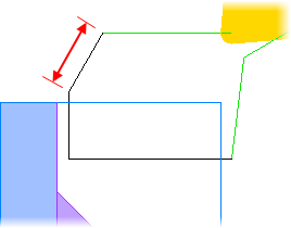
Back cutting engage radius — This is the radius of the arc at the beginning of each cut in a Back Cutting strategy. If use DOC is selected, this value is hidden.
Back cutting withdraw distance — This is the distance the tool withdraws at the end of each cut in a Back Cutting strategy, before returning for the next step.
Canned cycle X clearance — Enter the tool clearance in X before the start of a turning canned cycle. The tool location is obtained by applying the Canned cycle X clearance and Canned cycle Z clearance to the start point of the canned cycle. You must enable Use canned cycle to access this attribute.
Canned cycle Z clearance — Enter the tool clearance in Z before the start of a turning canned cycle. The tool location is obtained by applying the Canned cycle X clearance and Canned cycle Z clearance to the start point of the canned cycle. You must enable Use canned cycle to access this attribute.
Centerline overcut — Used with Turnmilling toolpaths. Enter the amount that the tool cuts past the centerline when cleaning up material against a shoulder at the end of a scan line. The default is 0.1 inches or 3 mm.
Chamfer extend dist. — This applies to Groove features and the relief groove operation for Thread features. Enter extra space for the tool so that it does not start on the metal.
Deflection — When using a cut grip style of finishing, enter the deflection by which you want to offset the cut.
Dwell — Enter the number of seconds that you want the tool to dwell after plunging. This applies during the Rough pass of a Groove feature, during a Cutoff chamfer, and during a Bar Feed feature.
End point — Set the point that the tool-tip center rapids to at the end of the operation.
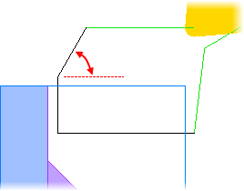
Engage angle — Enter the angle at which the tool enters the stock for boundary moves. This attribute is available for the rough pass if TNR comp is off. For the Semi-finish and Finish pass, this attribute is available on the Leads tab.
Finish passes — Normally this is set to 1 and a single pass is generated offset by the tool tip. If set to greater than 1, then the region to be finished is divided into equal parts and finished in sequential passes. The region to be finished is the X semi-finish allowance and the Z semi-finish allowance if the feature has a semi-finish pass, and it is the full X finish allowance and Z finish allowance if the feature has no semi-finish pass.
FPM — Enter the feed rate for a Bar Feed feature in IPM or MMPM.
Lead dist — Enter the distance for the lead-in and lead-out moves. This attribute is available for the Rough pass if you have selected TNR comp. on the Strategy tab. For the Semi-finish and Finish pass, see the Leads tab.
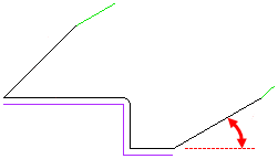
Lead-in angle — Enter the angle at which the tool enters the stock for boundary moves. This attribute is available for the rough pass if TNR comp is on. For the Semi-finish and Finish pass, this attribute is available on the Leads tab.
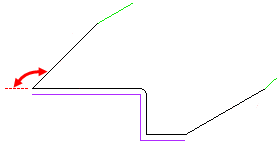
Lead-out angle — Enter the angle for the lead-out move, measured clockwise away from the part. An angle of 0 exits along the direction of path. An angle of 90 exits perpendicular to the path. This attribute is available when TNR comp is on. For the Semi-finish and Finish pass, this attribute is available on the Leads tab.
Peck retract dist. — For Cutoff and Groove features, Peck retract dist is the distance the tool retracts between plunges.
RPM — Enter the speed for Bar Feed features in RPM.
Side liftoff angle — Enter the angle to lift the tool off the part after each plunge cut. This increases the tool's life and leaves a better finish on the part. This attribute applies to a Groove feature.
Side liftoff dist — Enter the distance to move the tool after a plunge cut, in the direction opposite to the cutting direction. This increases the tool's life and leaves a better finish on the part. This applies to a Groove feature. See also Side liftoff angle.
Start point — Set the point that the tool-tip center rapids to at the start of the operation.
Stepover % — Enter the distance, as a percentage of the tool's diameter, that the tool shifts to position itself for the next plunge cut. This value specifies the maximum stepover distance. If this value evenly divides the width of the feature, it is used. If it results in a final pass that is quite shallow, the cut widths are adjusted to result in even roughing passes.
For example if you have a feature that is 0.5 inches wide and specify a width of cut of 0.4 (specified as a Stepover % of 80 for a tool with a diameter of 0.5 inches), the feature is roughed in two even passes 0.25 inches wide rather than one pass of 0.4 inches and another pass with a width of 0.1 inches.
Tool change location — Set the point where the tip of the tool moves to before a tool change.
This location is relative to the end of the curve.
Total stock — Enter an offset distance from the feature boundary to machine to instead of machining to the stock boundary. This option is available only for roughing operations of Offset type toolpaths.
Undercuts — Select from No checking, Adjust to tool geometry, and Remove all undercuts.
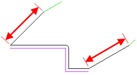
Withdraw angle — Enter the angle that the tool withdraws along before returning for the next step. The angle is measured in degrees, counter-clockwise from the Z axis. See also Withdraw length.
Withdraw length — Enter the distance along the Withdraw angle line that the tool withdraws before returning for the next step.
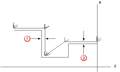
X finish allowance — Enter the amount of material to leave in the X direction after the Rough pass.
 Z finish allowance
 X finish allowance
X leave allowance — Enter the amount of material to leave in the X direction after the Finish pass.
Z leave allowance
X leave allowance
X semi-finish allowance — Enter the amount of material to leave in the X direction after the Semi-finish pass.
Z semi-finish allowance
X semi-finish allowance
Z finish allowance — Enter the amount of material to leave in the Z direction after the Rough pass.
Z finish allowance
X finish allowance
Z leave allowance — Enter the amount of material to leave in the Z direction after the Finish pass.
Z leave allowance
X leave allowance
Z semi-finish allowance — Enter the amount of material to leave in the Z direction after the Semi-finish pass.
Z semi-finish allowance
X semi-finish allowance