
- In the Modeling, Rigging, and Animation menu sets:
Deform >
(Create) Morph >

This topic covers the options in the Morph Options window. For information on using the Morph deformer, see Create a Morph Deformer.
Basic Tab
- Morph Mode
- Set how the Morph target object modifies the geometry.
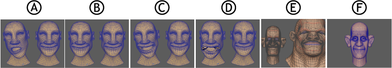
Morph modes: A. before deformation, B. Absolute, C. Relative, D. Surface, E. Retarget, and F. Mirror
-
Setting Behavior In the illustration above, (A) shows the geometry before the Morph deformer is applied. Absolute (B) Takes the exact value of the deformed object. Relative (C) Lets you modify your deformation relative to its current value. Surface (D) Matches the surface deformation. Note: If the deformation is very different from the source shape, the deformation may tear the geometry. If this occurs, activate the Neighbor settings to tweak the amount the target matches the source position. See the Neighbor settings in the Attribute Editor section at the end of this topic.Retarget (E) Lets you copy animation from one surface to another. (See Retarget animation with the Morph Deformer ) Mirror (F) Lets you reflect surface deformation on a specified axis. (See Mirror Geometry with the Morph deformer) - Morph Space
-
Use the Morph Space setting to define in what spacial context the morph occurs.
Setting Behavior Object Space Applies the source morph to the target object in its own spacial context. World Space Applies the source morph to the target object in the source objects spacial context, that is, the target object moves to occupy the same position as the source. - Use Original Morph Target
- This option is active only if you select the Relative Morph Mode.
- Use Component Lookup
- Derives the morph from the Source object geometry.
- Activate this option to automatically generate a componentMatch node in the Node Editor to be a component lookup table, letting you create complex correlations between the vert indices on the Source and target components, regardless of their position in the index table. See Create vert lookup tables with the componentMatch node.
- If you want to still create your own vert lookup tables and hook them up manually, do not activate Use Component Lookup.
- Component Match Tab
- When you select Use Component Lookup in the Attribute Editor Morph tab, a Component Match node is created that lets you create vert lookup tables.. See componentMatch node and Create vert lookup tables with the componentMatch node.
Advanced tab
See Advanced deformer options.
- Deformation Order
-
Specifies the placement of the deformer node in the deformable object’s history. For more information about deformer placement, see Advanced deformer options.
- Exclusive
-
Specifies whether the deformer set is in a partition. Sets in a partition can have no overlapping members. If on, the Partition To Use and New Partition Name options become available. Default is off.
- Partition To Use
-
Lists any existing partitions, and a default selection Create New Partition. If you select Create New Partition, you can edit the New Partition Name field to specify the name of a new partition. Only available if Exclusive is on.
- Partition Name
-
Specifies the name of a new partition that will include the deformer set. The suggested partition name is deformPartition, which will be created if it does not already exist. Typically, you might put all your exclusive deformer sets in the partition named deformPartition. However, you can create as many partitions as you like, and name them whatever you want. Only available if Exclusive is on.
Attribute Editor
Neighbor options
- Neighbor level
- Lets you set how many components beside the vertex the algorithm considers when smoothing jagged edges.
- Neighbor Exponent
- Lets you weight the effect of the Neighbor Level and the influence on the neighboring vertices. When set to 0, the distance has no effect. The higher the value, the more important nearby vertices become. Use this setting if your geometry "tears", as shown in the example above.
- Neighbor Bias
- Lets you add a fixed amount added to every distance so that vert distances that are near zero don't dominate the morph.
- Smooth Normals
- Filters abrupt changes to the geometry. Use this setting to generate softer-looking results.
- Mirror Direction
- Choose a reflection axis for the selected geometry. (This option is available only with the Mirror (Morph Mode.)
- See Mirror Geometry with the Morph deformer
Constraints
Use the Tangential constraints to create a smooth slippery morph effect. See Create a sliding effect with the Morph Deformer.
- Inward/Outward Constraint
- The Inward Constraint and Outward Constraint attributes limit the vert motion over the deformed surface. The Inward Constraint stops the vertex moving beneath the surface, while the Outward Constraint stops the vertex moving outside the surface to preserve the current geometry contour.
- Tangential Damping
-

- The Tangential Damping slider lets you control the effect of the deformer drawing geometry back to its input deformed shape whenever there is a large difference between the Inward constraint and Outward Constraint settings.
Retarget Scaling
Use Retarget Scaling to resize the retargeting effects.
See Retarget Geometry with the Morph Deformer.
- Scale Envelope
- Specifies the deformation scale factor. A value of 0 provides no deformation, a value of 0.5 provides a deformation effect scaled to half of its full effect, and a value of 1 provides the full deformation effect.
- Scale Level
- This slider controls all four settings below, letting you adjust how deep you want to apply the effect.
- Uniform Scale Weight
- This slider uses the overall scale of the surrounding verts to determine the size difference between the source and the target objects.
- Non-uniform scale instead separates it into separate scales in the tangential plane. For example, if square polygons on the source are sized 1 x 1 and rectangles on the target are 2 x 4, uniform scale interprets that as being scaled by 3, and non-uniform interprets it as being scaled by 2 in one direction and 4 in the other.
- Setting Uniform Scale Weight to 1.0 uses a total uniform scale interpretation, and setting it to 0.0 uses the non-uniform scale interpretation.
- Normal Scale
- This setting lets you adjust the retargeting effect along the normals direction. This setting is useful when retargeting objects that are different sizes.
-
In the example above, when you retarget from a smaller target object to a larger source, because the deformation is the same distance for both objects regardless of their size, a change made to the target may not appear as obvious on a larger surface. Adjust the Normal Scale setting to compensate.

- Tangent Plane Scale
- Provides a global, overall scaling effect to the source object.