Use the Point Cloud dialog to view and edit the details of a Point Cloud item.
To display the dialog, double-click the item's entry in the inspection sequence, or select its entry and press the Alt+Enter keys.
The dialog contains the following settings:
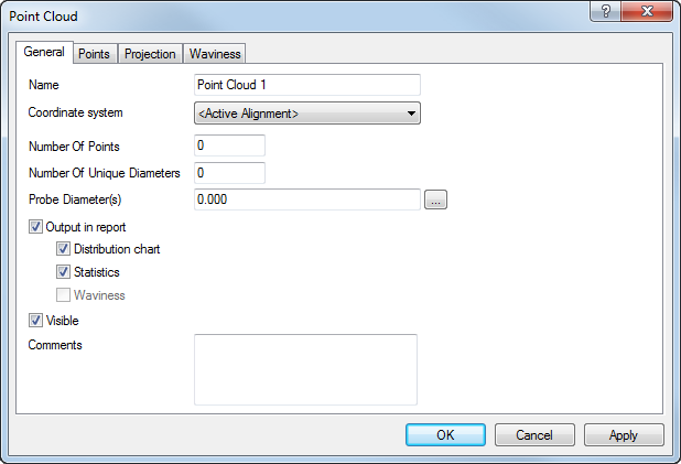
Name — Enter a name for the item. The name is used in the inspection sequence, in the Report and Info tabs, and when referencing the item in other items.
Coordinate system — Select the alignment relative to which the item's measurements are to be reported.
To specify the alignment during the inspection, select <Active Alignment>. You can then select the alignment from the Active alignment list, or by adding an Active Alignment item to the inspection sequence.
Number of points — Specifies the number of points in the point cloud.
Number of unique diameters — Specifies the number of different probes used to measure the points in the point cloud.
Probe diameters — Specifies the diameter of the probes used to measure the points in the point cloud. This value is used to calculate the offset of the probe centre from the probe surface. To specify the probe diameter for an imported point cloud, click
 , enter the diameter in the
New probe diameter box, and click
OK.
, enter the diameter in the
New probe diameter box, and click
OK.
Output in report — Select this check box to display the following in the report:
- Distribution chart — Select this check box to display the tolerance distribution for the point cloud.
- Statistics — Select this check box to display the statistics for the point cloud.
- Waviness — Select this check box to display the waviness percentage for the point cloud. The check box is selectable only when you select the Calculate waviness check box in the Inspection Point tab of the Measure Parameters dialog.
Visible — Select this check box to display the point cloud in the CAD view. Deselect the check box to hide the point cloud.
Comments — Use this box to record extra information about the point cloud.
Points — Lists the details of each point in the point-cloud. To remove points from the point-cloud, select their entries in the list, then click Delete Points.
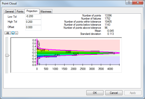
Projection — Shows the distribution of deviations from the CAD nominal.
Click:
 to show the distribution of all points in the point cloud.
 to zoom in to the graph.
 to zoom out of the graph.
Tolerances — Enter a value in the Low Tol box and in the High Tol box to specify the in-tolerance range for the point cloud. When you have specified the tolerances for a point cloud:
- Green indicates the measurement is within the tolerance band.
- Red indicates the measurement is above the tolerance band.
- Blue indicates the measurement is below the tolerance band.
Offset — Specifies the surface offset of the points in the point cloud. The offset is normal to the surface at the probed point, with positive values offsetting in the direction of the probe.
Waviness — Waviness describes the widely spaced irregularities that can result from problems with the manufacturing process, for example, machine vibration. For each point, PowerInspect calculates the difference between the highest and lowest surrounding points within a specified diameter. It then reports the number of differences lying within a specified maximum value as a percentage of the total points: the higher the percentage waviness, the smoother the surface.
Enter the:
- Width to specify the comparison diameter.
- Maximum to specify the waviness tolerance.
Click OK to close the dialog and save your changes.