Use the PowerInspect DRO to display the location of the probe on the measuring device. You can also use the DRO to display the location and vector of triggered points and to measure distances between points along the device axes.
Note: The PowerInspect DRO only supports measuring devices that include a tracking point facility; without this facility, it can only determine the location of triggered points. It is available only for use with CNC and Manual machines.
 tri
tri
To use the PowerInspect DRO:
- Click Tools tab > Machine panel > DRO.
- Align the axes of the part you want to inspect with the axes of the measuring device.
- Connect PowerInspect to the measuring device.
- Home the measuring device.
- Select Tools tab > Machine panel > DRO.
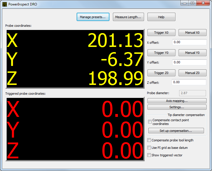
- Click Axis mapping to align the DRO axes with the axes of the measuring device.
- Click Settings to configure the PowerInspect DRO.
- By default, the PowerInspect DRO displays the coordinates of the probe centre. To display the coordinates of the touch point, select the Compensate contact point coordinates check box, and click Set up compensation to specify how the compensation is to be applied.
- By default, the DRO reports the position of the end of the quill. Select the Compensate probe tool length check box to report the position of the probe tip.
- By default, the probe coordinates are reported relative to the home position of the measuring device. To display the coordinates relative to:
- the datum of PowerInspect's current grid mode, select the Use PI grid as base datum check box.
- a specified position, use the trigger and manual buttons to zero the PowerInspect DRO.
- To display the vector of the trigger point as well as the trigger point coordinates, select the Show triggered vector check box.
- Move and trigger the probe. The Probe coordinates box displays the location of the probe as it moves; the Triggered probe coordinates displays the location of the last triggered point.
- To save the current settings for future use, click Manage presets.
- To measure the distance between two points, click Measure length.
Note: If you specify a
Scale Factor in the
Measure Parameters dialog, it is displayed below the Probe coordinates.