The Free Form Fit alignment enables you to align a part to the CAD model using measured dynamic points. Use it when you need to inspect parts, such as pressings, that have no clearly definable features for which the nominals are known.
To create a Free Form Fit alignment:
- Insert dynamic points on the CAD model using the Dynamic Points Editor. The points must:
- fix the part's six degrees of freedom.
- have a normal that represents the direction from which the point will be probed.
- be surface points.
- have the correct offset value.
- Click Dynamic Points tab > Items panel > Free Form Fit Alignment. The details of the points you selected are displayed in the
Free Form Fit Alignment dialog.
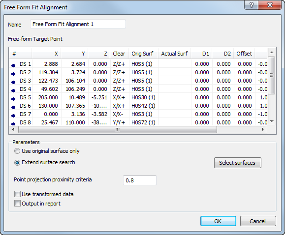
- Enter a Name for the alignment.
- By default,
PowerInspect projects each point onto the surface nearest its measured position. To:
- restrict the surfaces on which the points can be projected, click Select surfaces and use the CAD Object Selection dialog to deselect the surfaces that must not be used.
- restrict the points to the surfaces on which you placed them, select Use original surface only.
- change the search radius for the nearest surface, enter a new value in the Point projection proximity criteria box.
If no available surfaces are within the search radius, the point is ignored.
- If the inspection sequence contains constructed features that use measurements taken by different measuring devices or from different device positions, select the
Use transformed data check box.
When you select this check box, PowerInspect converts the device coordinates to CAD coordinates so that all calculations are made using a common reference system. You must select this check box in all alignments that contain items used in constructed features.
Selecting this check box has no effect when all coordinates in the inspection are collected with one measuring device in one position, or when the inspection sequence contains no constructed features.
- To include the details of this item in the report, select the Output in report check box.
- Click OK to save your changes and close the dialog.
- If delay measure is not active,
PowerInspect displays the CAD view in full screen mode, so you can measure the alignment. For example:
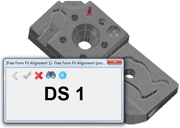
- Probe each point shown in the CAD display. Click:
 to delete the details of the last point you probed.
 to calculate the alignment from the measured points.
 to exit probing mode without calculating the alignment.
PowerInspect creates an alignment item in the inspection sequence.
to exit probing mode without calculating the alignment.
PowerInspect creates an alignment item in the inspection sequence.
 to display the probe point perpendicular to the point's normal.
 to redisplay the
Free Form Fit Alignment dialog.
to redisplay the
Free Form Fit Alignment dialog.