Use the Probed Torus item to measure a torus or partial torus on a part. You must measure a minimum of nine points distributed over the torus with three points along the major circle, three points along the minor circle, and the remaining points around the torus.
To create a Probed Torus item:
- Open a Geometric group in the Sequence Tree.
- Click Geometry tab > Features panel > 3D > Probed Torus.
The Probed Torus dialog contains the following areas:
Name — Enter a name for the item. The name is used in the inspection sequence, in the Report and Info tabs, and when referencing the item in other items.
Use nominals — Select this check box to enter or change the item nominals, and to compare the item measurements to their nominal values. Deselect this check box to disable comparisons with the item nominals.
When this check box is selected, an in-tolerance
 or out-of-tolerance
 indicator is displayed on the measured item's icon in the inspection sequence; the border of the item
label is coloured to indicate whether the measurements are within tolerance; and the tolerance, nominal, deviation, and error values of the item are shown in the report.
indicator is displayed on the measured item's icon in the inspection sequence; the border of the item
label is coloured to indicate whether the measurements are within tolerance; and the tolerance, nominal, deviation, and error values of the item are shown in the report.
When this check box is deselected, the Nominal boxes are disabled, no tolerance indicators are displayed and no tolerance, nominal, deviation, and error values are shown in the report for this item.
 and select
From CAD Entity. To replace the nominals with the item's measurements in the current Measure, click the button and select
From Active Measure.
and select
From CAD Entity. To replace the nominals with the item's measurements in the current Measure, click the button and select
From Active Measure.
Visible — Select this check box to display the item in the CAD view.
Output in report — Select this check box to include the item in the report.
Coordinate system — Select the alignment relative to which the item's measurements are to be reported.
To specify the alignment during the inspection, select <Active Alignment>. You can then select the alignment from the Active alignment list, or by adding an Active Alignment item to the inspection sequence.
Material side — Choose the side from which you want to probe the feature. Select:
- Hole (ID) to probe an internal feature.
- Boss (OD) to probe an external feature.
- Not specified to leave the probing direction unrestricted.
 Start angle — Enter the start angle of the feature relative to the
Orientation vector. You can enter the angle in degrees or radians.
Start angle — Enter the start angle of the feature relative to the
Orientation vector. You can enter the angle in degrees or radians.
 End angle — Enter the end angle of the feature relative to the
Orientation vector. You can enter the angle in degrees or radians.
End angle — Enter the end angle of the feature relative to the
Orientation vector. You can enter the angle in degrees or radians.
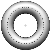
Major diameter — Enter the nominal and tolerances for the Radius or Diameter of the major circle. The dotted line indicates the major circle of the torus:
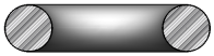
Minor diameter — Enter the nominal and tolerances for the Radius or Diameter of the minor circle. A section through the torus shows its minor circle:
Centre — Enter the nominal and tolerances for the position of the feature's centre point.
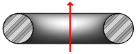
Direction vector — Enter the nominal direction of the main axis. The red arrow indicates the vector of the torus.
To reverse the vector, click the Invert vector  button.
Profile — Enter the Maximum difference between the points with greatest positive deviation and greatest negative deviation from the best-fit torus. If the difference between the greatest positive deviation and the greatest negative deviation exceeds the Maximum value, the profile is out-of-tolerance.
Orientation — Specify the vector from which the Start angle and End angle are calculated when creating a partial torus.
Auto-accept enabled — Select this check box to save the item measurements as soon as you have probed the number of points specified in the Points box. If you played the item as part of the inspection sequence, PowerInspect automatically plays the next item. Deselect the check box to choose how many points to probe and save your measurements manually. This option is available only when an item has no probe path.
Point sources — Select this tab to use probed points from other items to measure this item.
For example, you can use the tab to create a measured cylinder by combining measurements from probed circles at the top and bottom of the feature.
To specify the sources for the probed points, select one or more items in the
Available sources list, and then click
 to add them to the Selected
sources
list.
to add them to the Selected
sources
list.
To remove sources, select the items in the
Selected sources list, and then click
 .
.
Click OK to close the dialog and save your changes.