Use Collision Avoidance Parameters to specify the parameters for Collision Free Link Path items.
When a Collision Avoidance Parameters item is at the Definition level of the inspection sequence, the changes apply to all following Collision Free Link Path items until they are changed by another Collision Avoidance Parameters item. When an item is added to a group, the changes affect only the following Collision Free Link Path items in that group.
Click Home tab > Probe Path panel > Link > Collision Avoidance Parameters to display the Collision Avoidance Parameters dialog.
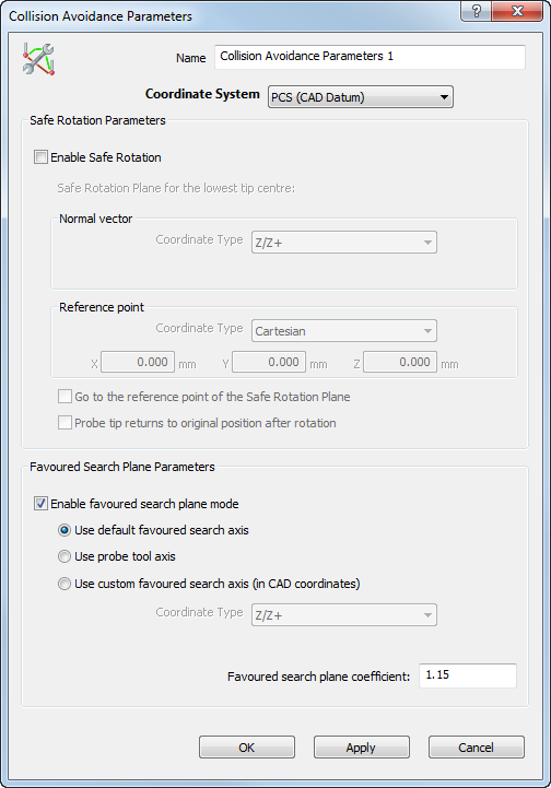
It contains the following areas:
Name — Enter a name for the item. The name is used in the inspection sequence, in the Report and Info tabs, and when referencing the item in other items.
Coordinate system — Select the alignment relative to which the item's measurements are to be reported.
To specify the alignment during the inspection, select <Active Alignment>. You can then select the alignment from the Active alignment list, or by adding an Active Alignment item to the inspection sequence.
Enable Safe Rotation — Select this check box to specify a Safe Rotation Plane. The tip of the probe stays higher than the Safe Rotation Plane during any angle rotation.
Go to the reference point of the Safe Rotation Plane — Select this option to always drive the rotation centre (not the tip) of the probe head over the reference point of the Safe Rotation Plane.
Probe tip returns to original position after probing — Select this option if your machine automatically compensates the position of the probe tip during or after a rotation. If selected, the probe path continues from the same point after performing a rotation.
Before rotation:

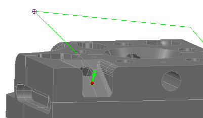
After rotation:
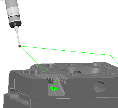
The probe rotation point is marked on the probe path with a target icon:
Deselect this option if the probe tip of your machine does not compensate the position of the probe tip. If deselected, the probe path continues from the new position of the probe tip after rotation.
Before rotation:
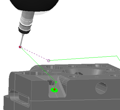
After rotation:
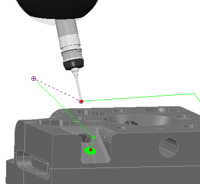
A purple dashed line joins the positions of the probe before and after the rotation.