Activity 2: Specify a design space
In this activity, you specify the design space by determining which geometry to include in generative design process and which geometry exclude from it. Additionally, you use a starting shape to optimize an existing bracket.
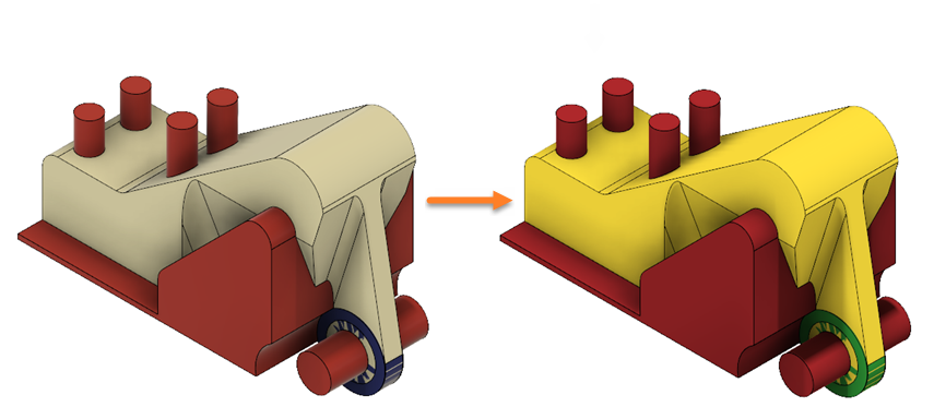
The ALCOA Bracket opened (left) and the model with all geometry types assigned (right).
Prerequisites
- Activity 1 is complete.
Steps
Assign a starting shape to the Original Shape component.
Note: The starting shape is a type of geometry you apply to a body that is modified according to the goals and constraints during the generative design process.- On the Define tab, click Design Space > Starting Shape
 .
. - On the canvas, select the body highlighted in blue as shown in the following image.
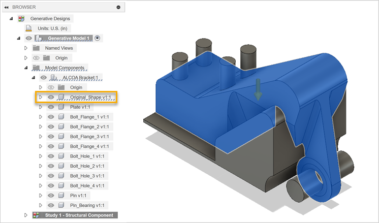
Note: In the browser, you can see that the Original Shape component is highlighted too. - In the Starting Shape dialog, ensure that Add/Remove Material option is selected, and click OK.
The body displays in yellow on the canvas.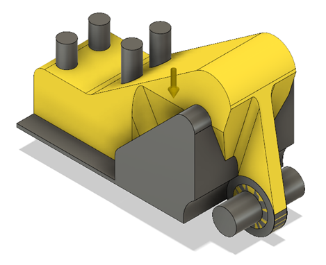
- To verify that the body is assigned as the starting shape in your design, in the Browser, under Study 1 - Structural Component, expand Starting Shape.
Tip: To modify, mouse over the Starting Shape node in the Browser, and then click .
. - To hide the starting shape on the canvas, click
 next to the Original Shape component.
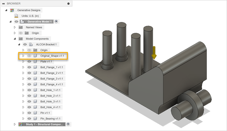
- On the Define tab, click Design Space > Starting Shape
Assign a preserve geometry to the Bolt Flange and Pin Bearing components.
Note: The preserve geometry is a type of geometry that you apply to a body you want to include in the final shape of your design.- On the Define tab, click Design Space > Preserve Geometry
 .
. - On the canvas, select the bodies highlighted in blue as shown in the following image.
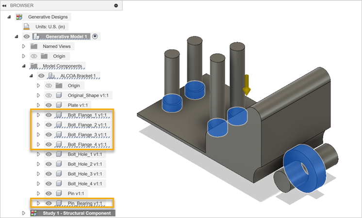
Note: In the browser, you can see that the Bolt Flange and Pin Bearing components are highlighted too. - In the Preserve Geometry dialog, click OK.
The bodies display in green on the canvas.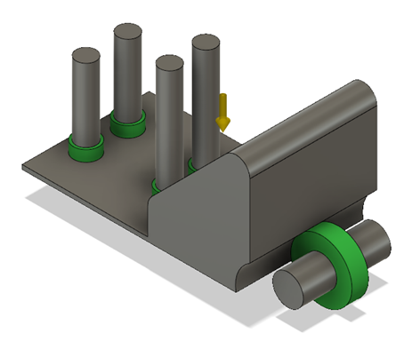
- To verify that 5 bodies are assigned as preserve geometries in your design, in the Browser, under Study 1 - Structural Component, expand Preserve Geometry.
Tip: To modify, mouse over the Preserve Geometry node in the Browser, and then click .
.
- On the Define tab, click Design Space > Preserve Geometry
Assign an obstacle geometry to Plate, Bolt Hole, and Pin components.
Note: The obstacle geometry is a type of geometry that you apply to a body you want to exclude from the final shape of your design.- On the Define tab, click Design Space > Obstacle Geometry
 .
. - On the canvas, select the bodies highlighted in blue as shown in the following image.
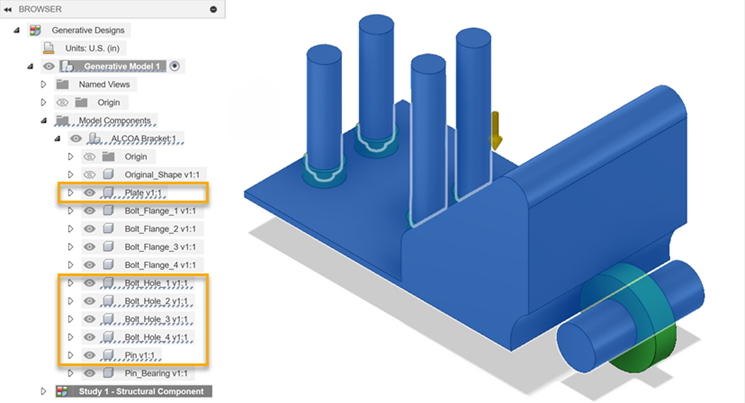
Note: In the Browser, you can see that the Plate, Bolt Hole, and Pin components are highlighted too. - In the Obstacle Geometry dialog, click OK.
The bodies display in red on the canvas.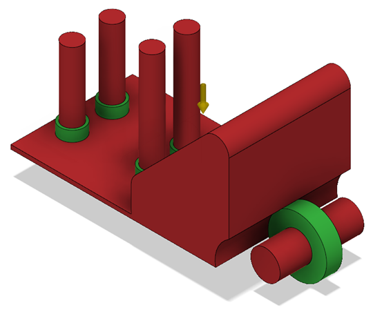
- To verify that 6 bodies are assigned as obstacle geometries in your design, in the Browser, under Study 1 - Structural Component, expand Obstacle Geometry.
Tip: To modify, mouse over the Obstacle Geometry node in the Browser, and then click .
.
- On the Define tab, click Design Space > Obstacle Geometry
Activity 2 summary
In this activity, you specified the design space by assigning the geometry types to the ALCOA bracket model.
Additional tips on starting shapes
| Quick Tip: How to Use Starting Shapes in Generative Design | Quick Tip: Advanced Starting Shapes in Generative |