Activity 3: Apply constraints and loads
In this activity, you specify a design conditions by applying constraints and loads to the selected geometry. You create three different load cases. You clone a load case and modify an existing load.
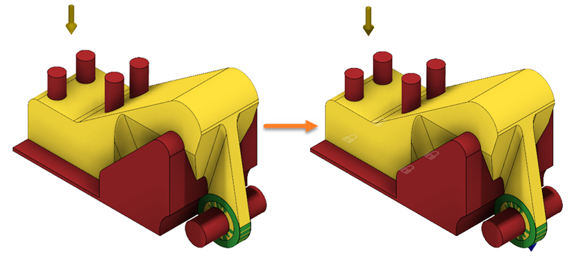
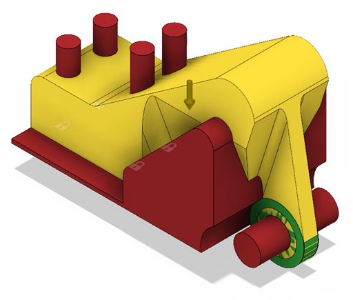
The ALCOA Bracket model with all geometry types assigned (left) and the model with constraints and loads applied (right).
Prerequisites
- Activity 2 is complete.
Steps
Apply a fixed constraint to the bottom faces of the Bolt Flange components.
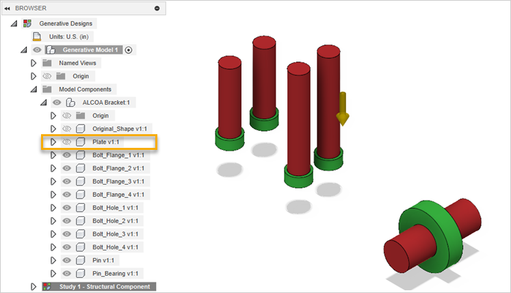
- To hide the plate on the canvas, in the Browser, click
 next to the Plate component.
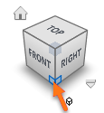
- To change the current view, click the bottom-right corner of the ViewCube.
- On the Define tab, click Design Conditions > Structural Constraints
 .
.
Warning: You can apply constraints to preserve geometries only. - In the Structural Constraints dialog, verify that Fixed constraint is selected.
- On the canvas, select the faces highlighted in blue as shown in the following image.
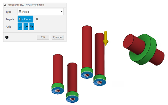
Note: The padlock icons display on the selected faces. - In the Structural Constraints dialog, click OK.
- To verify that the constraint is applied correctly, in the Browser, expand Load Case1 > Constraints.
Tip: To modify the applied constraint, do one of the following:- Mouse over it in the browser, and then click
 .
. - On the canvas, double-click the padlock icon.
- Mouse over it in the browser, and then click
- To return to the Home view, move the cursor over the ViewCube, and click
 Home.
Home. - To display the hidden components on the canvas, in the Browser, click
 next to the Plate and Original Shape components.
- To hide the plate on the canvas, in the Browser, click
Apply a force load to the interior face of the Pin Bearing component.
- On the canvas, select the body highlighted in blue as shown in the following image.
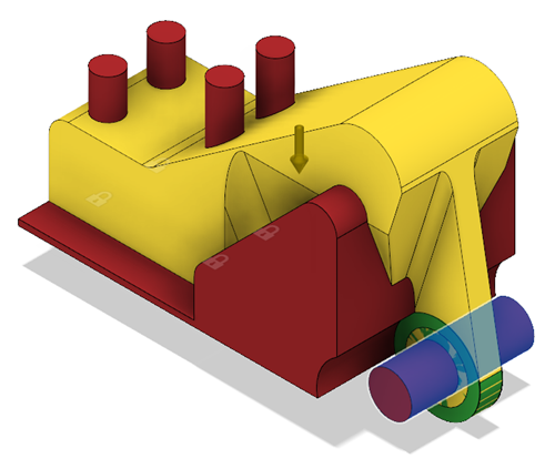
- To hide the pin on the canvas, in the Browser, click next to the Pin component.
- To deselect the body, click anywhere on the canvas.
- On the Define tab, click Design Conditions > Structural Loads
 .
.
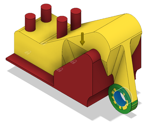
Warning: You can apply loads to preserve geometries only. - In the Structural Loads dialog, verify that Force load is selected.
- On the canvas, select the face highlighted in blue as shown in the following image.
- To change the current view, click the Front of the ViewCube.
- In the Structural Loads dialog, for Direction Type click the Vectors (x, y, z) icon
 .
. - In the Fx input field, enter 1250.
The arrow displays on the selected face as shown in the following image.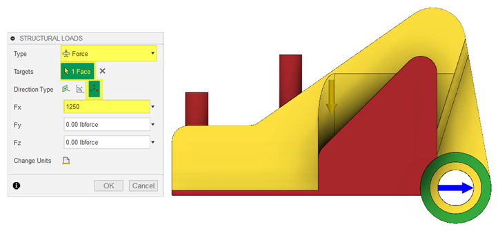
- Click OK.
- To verify that the force load is applied properly, expand Load Case1 > Loads.
Tip: To modify the applied load, do one of the following:- Mouse over it in the browser, and then click .
- On the canvas, double-click the arrow icon.
- Mouse over it in the browser, and then click
- On the canvas, select the body highlighted in blue as shown in the following image.
Clone the load case 2 times.
- In the Browser, right-click Load Case 1 and select Clone Load Case from the context menu.
Load Case 2 appears in the Browser. - Repeat the previous step to create an additional load case.
Load Case 3 appears in the Browser.
- In the Browser, right-click Load Case 1 and select Clone Load Case from the context menu.
Modify the Force2 load for Load Case 2.
- Double-click Load Case 2 to activate this load case.
Load Case 2 is highlighted in blue in the Browser. - In the Browser, expand Load Case 2 > Loads.
- Mouse over Force 2, and then click .
- In the Fx input field, enter 662, and in the Fz input field, enter -662.
The arrow displays on the selected face as shown in the following image.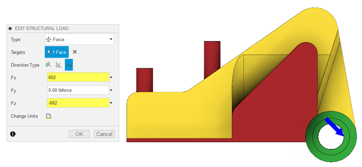
- Click OK.
- Double-click Load Case 2 to activate this load case.
Modify the Force3 load for Load Case 3.
- In the Browser, right-click Load Case 3, and select Activate Load Case from the context menu.
Load Case 3 is highlighted in blue in the Browser. - In the Browser, expand Load Case 3 > Loads.
- Select Force 3, and then click .
- In the Fx input field, enter 0, and in the Fz input field, enter -2500.
The arrow displays on the selected face as in the following image.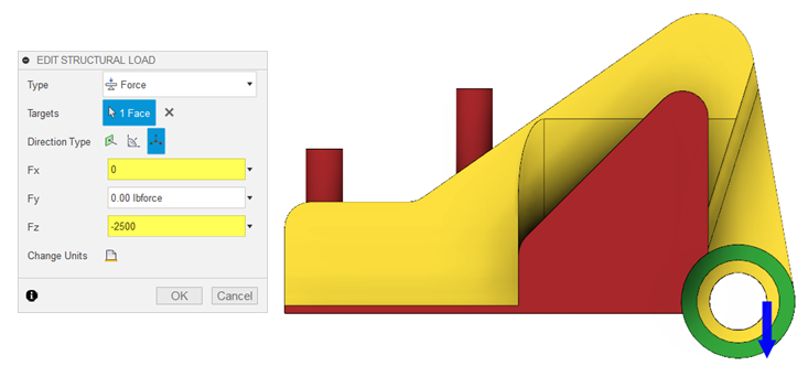
- Click OK.
- To display the pin on the canvas, in the Browser, click next to the Pin component.
- To return to the Home view, move the cursor over the ViewCube, and click Home.
- In the Browser, right-click Load Case 3, and select Activate Load Case from the context menu.
Activity 3 summary
In this activity, you specified a design conditions by applying constraints and loads to the selected geometry.