
Use the Emitter Objects panel to configure emitter parameters.
Emitter Parameters rollout
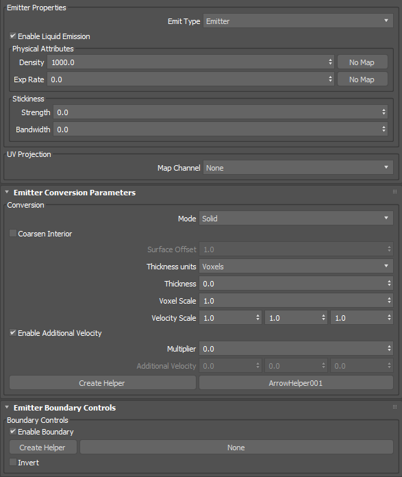
Emitter Properties group
- Emit Type
- Sets the emit type, either emitter or container. An emitter continuously emits liquid, while a container only emits once like a swimming pool or a bottle of water for example.
- Enable Liquid Emission
- When enabled, allows the emitter to produce liquids. This parameter can be animated.
Physical Attributes
- Density
- Sets the physical density of the fluid. For example, water has a higher density than oil.
Warning: In simulations using smaller scales (such as inches) with Surface Tension enabled, values of less than 1 may cause the fluid to form clumps and the simulation to run very slowly. In addition, the system may become unstable.
- Exp Rate
- Expands or contracts the liquid within the emitter. Positive values push particles out of the emitter in all directions while negative values pull particles in. A value of 0.0 neither pushes nor pulls.
For example, if your Emit Type is set to Emitter and you are trying to fill a glass from the bottom up, set the Exp Rate to a positive amount.
Stickiness
- Strength
- Sets the amount that the fluid from this emitter adheres to nearby colliders.
- Bandwidth
- Sets, in world-space units, how close the fluid from this emitter must be to a collider in order for the stickiness to affect it.
UV Projection group
- Map Channel
- Sets a map channel for projecting UVs onto the liquid volume, which can be useful when simulating textured liquids such as lava or cement. Using higher resolution meshes will yield the best results.
Note: When rendering a simulation using projected UVs, you must also remember to add the channel in the Add Channels list of the Render Settings panel if you are using any option other than Arnold Surface.
Emitter Conversion Parameters rollout
Conversion group
- Mode
- Controls how the emitter is voxelized, either Solid, Shell, or Solid (Robust).
- Solid creates a solid volume including the mesh interior. The mesh should be both manifold and watertight.
- Shell create a thin shell around the mesh surface. In this mode, Thickness should typically be 1.0 or more.
- Solid (Robust) is an alternative to Solid that usually gives better results for volumes with fine detail, openings leading to cavities, or non-watertight surfaces. However, this setting does not handle fluids inside completely enclosed regions.
- Coarsen Interior
- Saves memory by performing additional coarsening of the voxels inside the volume when the conversion mode is Solid (Robust), especially with self-intersecting meshes.
- Surface Offset
- Sets the distance in voxel widths used to close (dilate and then erode) the solid voxels when the conversion mode is Solid (Robust). The internal minimum is 1.0 so that only greater values have an effect. Note that high values can create artifacts.
- Thickness Units
- Sets whether thickness is in voxels or world-space units. When set to Voxels, the effective thickness depends on the Base Voxel Size setting of the simulation.
- Thickness
- Sets the amount to thicken the mesh. For solid shapes that are already quite thick, you can use 0.0 for a precise boundary or even negative values to shrink along the surface normals. For thinner volumes and shells, you should use larger values to prevent holes.
- Voxel Scale
- Sets a scaling factor for the base voxel size used to initially voxelize meshes that share this property.
- Velocity Scale
- Controls the proportion of velocity that is inherited from the emitters' animated transformation and deformation by the fluid at the time of emission in each of the world X, Y, and Z axes.
- Enable Additional Velocity
- Adds extra velocity to any existing velocity from other sources (such as velocity inherited from the emitter's animation).
- Multiplier
- Sets a multiplier to scale additional velocity uniformly across all axes.
- Additional Velocity
- Sets the base velocity to add in world coordinates.
- Create Helper
- Creates an arrow helper object in the scene. The orientation of the arrow adjusts the direction of the additional velocity.
Note: You can link Arrow helpers directly to custom emitters, however not to the standard sphere, box, or plane emitters. This is because these emitters are in fact world-space objects that are part of the simulation. If you wish to link an arrow helper to a standard emitter, use the procedure found in the Frequently Asked Questions topic, linked at the bottom. You can still use the Arrow helper to provide direction for a standard emitter, but it should not linked to the simulation object.
- None
- Picks an Arrow helper already added to the scene. The button will update with the name of the currently-selected helper.
Emitter Boundary Controls group
- Enable Boundary
- Enables boundary control to limit the area from which fluid is emitted.
- Create Helper
- Creates a Volume helper object in the scene. The valid types for boundaries are Box and Sphere.
- None
- Picks a Volume helper already added to the scene. The button will update with the name of the currently-selected helper.
- Invert
- Inverts the area of the boundary.