
Load Drop in Compression
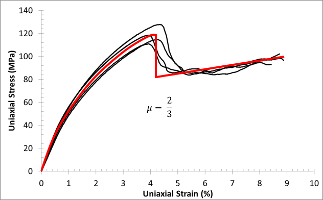
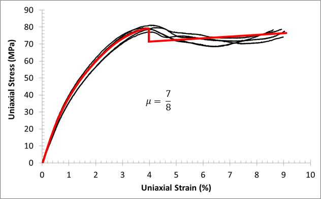
Earlier we saw experimental data showing how the material exhibits a load drop under compression. Let's call the magnitude of this load drop μ. The value of μ varies as the loading angle changes. Therefore, we need a method to determine μ for any stress state that triggers the compressive failure criterion.
0°:
90°:
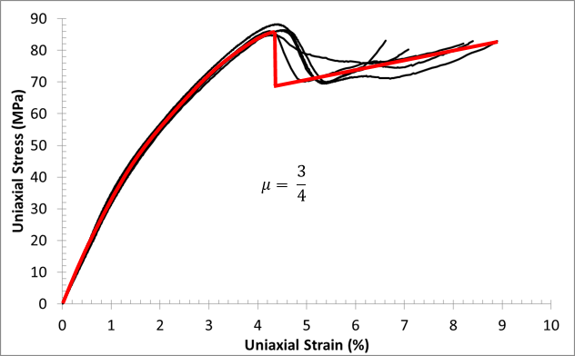
45°:
Determine μ
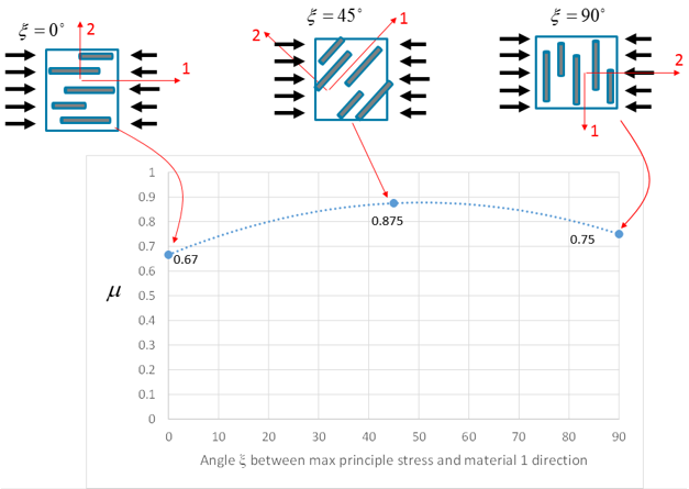
The first step is to determine the principal stresses (σI ≥ σII ≥ σIII) and principal directions (âI, âII, âIII) of the matrix stress state that triggered the compression failure criterion. The third principal stress (σIII) will always be the compressive stress with the largest magnitude. Next, we determine the angle between the third principal direction (âIII) and the principal material direction. We denote this angle as ξ.
Now we write μ as a quadratic function of the angle ξ.
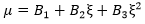
where the coefficients B1, B2, and B3 are determined from load drops in the three experimental stress-strain responses. Using the three known input angles, ξ (0, 90, 45), and the measured load drops, μ for each curve, we can solve a system of equations to determine the coefficients B1, B2, and B3. These coefficients are used during the structural analysis to determine the appropriate load drop to apply for any given stress state that triggers the compressive failure criterion.
The image below shows an example of how μ is dependent on the direction of the principal compressive stress relative to the principal fiber orientation.
Damage Evolution
After we have determined μ for the stress state that triggers failure, we can apply it to the composite stress. The stiffness of the composite material is instantaneously reduced by multiplying the stiffness matrix by the fraction μ. After μ is applied, the plasticity response continues to evolve as before.