
Assemblies
This section describes some special considerations for using structural assemblies with Advanced Material Exchange.
The Advanced Material Exchange Interface
When you are working with a structural assembly, you must map parts, map results, and characterize the nonlinear material (if applicable) for each body of the assembly. For example, let's assume we have a structural assembly with 3 bodies: Part1, Part2, and Part3. We have a unique Moldflow study for each of these 3 bodies: MF_Study1, MF_Study2, and MF_Study3. In this case, we would pair Part1 with MF_Study1, map the results between these two files, and characterize the material if an elastic-plastic material model is used. Next, we would pair Part2 with MF_Study2, map the results between these two files, and characterize the material. We would repeat this process for Part3 and MF_Study3 as well. The steps required to map parts, map results, and characterize the material is the same whether you use an assembly or a single-part.
Once all of the bodies in an assembly have been paired, results have been mapped, and the materials have been characterized, you can export for structural analysis. Before exporting, be sure to select an environment for any nonlinear material that was characterized.
It is worth noting that only the bodies of the structural assembly that have a corresponding Moldflow study need to be mapped. For example, let's assume we have two injection molded parts, MF_Study1 and MF_Study2, that are joined by a metal pin. Our structural assembly would contain all 3 bodies, but we don't need to consider the metal pin in Advanced Material Exchange.
Edit an Assembly
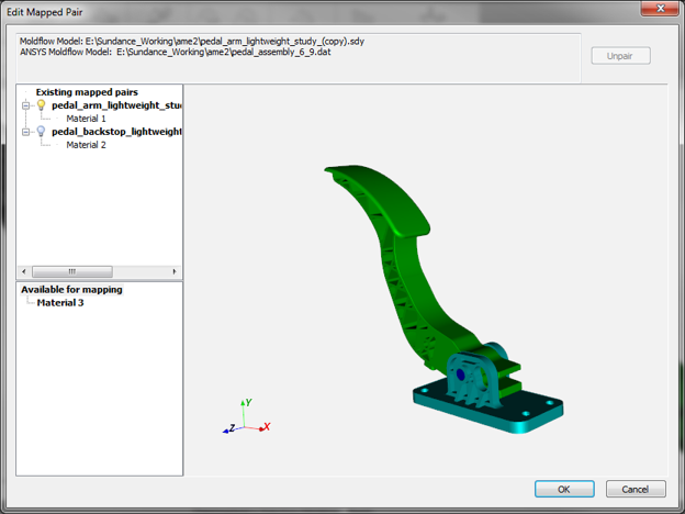
After you have paired one or more parts in your structural assembly, you may need to edit the mapped pairs.
- Click
 (Home > Assembly > Edit). In the Edit Mapped Pair dialog, you will see all of the existing mapped pairs and any available bodies in the structural assembly that are still available for pairing. The active mapped pair in the display window is denoted by the lightbulb icon
  .
. - To edit a mapped pair, select a pair and click Unpair.
- Click OK when you are finished editing the existing mapped pairs.
Display Mapped Pairs
After you have paired one or more parts and have mapped results between the parts, it can be useful to switch the active pair in order to visualize fiber orientations, residual strains, and weld surfaces.
- Click
 (Home > Assembly > Display).
 - Select a different mapped pair to display from the Display drop-list. The selected pair will become the new active pair.