
Use the Pattern finishing page to create a toolpath using the projection of a pattern onto the model. The pattern is defined by pattern curves. To specify the profile curves you want to use as pattern curves, double-click the profile curves in the CAM Face window to display the Curve Properties dialog.
Lower limit determines the lowest position of the machining pass.
The following examples show a treble clef pattern on a model:
Base position — Select the option to determine how to project the pattern onto the model and to determine the lowest position of the toolpath.
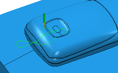
- Automatic — Drops the tool onto the part down the tool axis. This gives the same results as Drop when the tool axis is Vertical.
If you have a different tool axis, you get a different result:

- Drop — Drops the tool onto the part. It drops the tool down the Face plane normal.
This gives the same results as using the Automatic base position when the tool axis is Vertical.
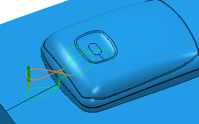
- Drive curve — The pattern is not dropped onto the model. The toolpath follows the pattern.
- Axial offset — Enter the distance to offset the pattern along the tool axis. For the toolpath to be above the pattern enter a positive value. Zero depth is where the tool tip touches the pattern. This option is available only if you select a Base position of Drive curve.
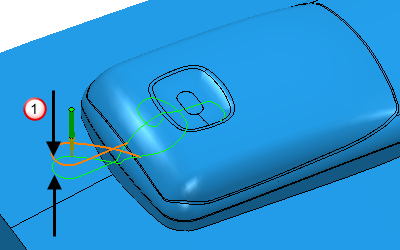
 Axial offset
Tolerance — Enter a value to determine how accurately the toolpath follows the contours of the model.
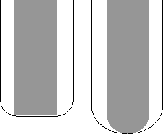
Thickness — Enter the amount of material to be left on the part. Clicking the Thickness  button changes the Thickness field to Radial thickness
  and the Axial thickness
  field appears. Use this to specify separate Radial and Axial thickness values
  .
.
Thickness — Enter the amount of material to be left on the part, within tolerance. This is an offset to the tool in all directions.
Thickness applies the thickness as an offset to the tool in all directions:
 Radial thickness — Enter the radial offset to the tool. When 2.5-axis or 3-axis machining, a positive value leaves material on vertical walls.
Axial thickness — Enter the offset to the tool, in the tool axis direction only. When 2.5-axis or 3-axis machining, a positive value leaves material on horizontal faces.

Variable thickness (that is, separate Radial and Axial thickness values) is useful for orthogonal parts. You can use variable thickness on sloping walled parts, although it is more difficult to predict the results.
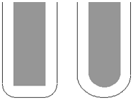
In thin-walled parts, you may want to finish the floor of the pocket, but to leave material on the thin vertical walls. In this case, specify a positive Radial thickness value and an Axial thickness of 0:
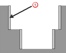
Radial thickness
Alternatively, you can also use this method to finish the steep side walls and leave material on the bottom. In this case, specify a Radial thickness of 0 and a positive Axial thickness value:
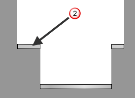
 Axial thickness
Typically, variable thickness is used on flat-bottomed parts with pockets.