
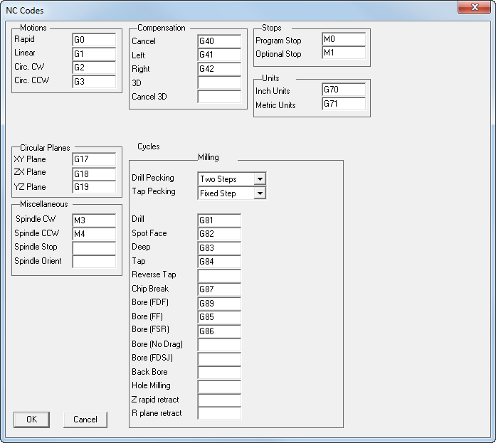
Specifies the exact character strings for different NC commands. The NC Codesdialog is displayed.
You can specify the following parameters:
Motions — The options in this section describe motion types required by the NC machine. All of these codes must be specified.
For example, Linear is generally defined as G1, but may be changed to G01, or any other string (up to 11 characters). All motion commands are passed to Post via the string reserved word <MOTION>.
The following options are available:
- Rapid - rapid move.
- Linear - feed move.
- Circ. CW - circular interpolation, clockwise.
- Circ. CCW - circular interpolation, counter-clockwise.
- XY, UV - refers to Wire EDM 4-axis movements using an upper and a lower curve. Typically, XY represents the curve at the bottom of the part, and UV represents the curve at the top of the part.
Compensation — This generates cutter diameter compensation in the output when enabled in FeatureCAM, and if it is built into the CNC data file.
Compensation selections use the string reserved word <COMP-STAT> for one of the below options, or an empty string is assigned if Compensation was not turned On in FeatureCAM.
The Compensation frame has these options:
- Cancel - compensation off.
- Left - compensation on cutter, applied to left in direction of travel.
- Right - compensation on cutter, applied to the right in the direction of travel.
- 3D - code for turning 3D cutter compensation on. Linear X, Y, Z motions have a vector component of the tool diameter added according to the direction vector defined by I, J, K.
Note: This applies to finishing moves only.
This code does not apply to Wire EDM.
- Cancel 3D - turns off 3D cutter compensation.
Note: This code does not apply to Wire EDM.
Units — Specify the G codes that set the post to Inch Units or Metric Units. The reserved word <UNITS> outputs the current value specified by the user. Typical values are G20/G21 or G70/G71.
Circular planes — This is used for circles described in XY, ZX, YZ Cartesian planes.
Pecking — This selects types of pecking performed for drilling and tapping.
Miscellaneous — The options in this section contain codes used for coolant and spindle specifications.
- Cool OFF — coolant off.
- Cool Mist — coolant on, mist.
- Cool Flood — coolant on, flood.
- Coolant 3 — user-configurable coolant code (for example, you can use it to turn on the air blast).
- Coolant 4 — user-configurable coolant code.
Note: The coolant options use the string reserved word <COOLANT>
- Spindle CW — spindle on, start clockwise.
- Spindle CCW — spindle on, start counter-clockwise.
Note: The spindle options use the string reserved word <SPINDLE>
- Spindle Stop — stops spindle.
- Spindle Orient — orients spindle.
Cycles — The options in this section describe canned cycles formats.
They are used for header, canned motion, and cycle cancel blocks. The header block (for all canned cycles) must contain formats to position down to the clearance plane to drill the first hole.
- Drill pecking - Select the type of drill pecking from Fixed Step, Two Steps, Value Reduction, or Factor Reduction.
- Tap pecking - Select the type of drill pecking from Fixed Step, Two Steps, Value Reduction, or Factor Reduction.
Enter G-codes for all drilling cycles. If no G-code is entered, FeatureCAM generates a computed cycle for that operation.
- Drill - specifies the header block for a drilling cycle.
- Spot Face - specifies header block for a spot face cycle.
- Deep - specifies a deep hole cycle header block.
- Tap - specifies the header block for a tapping cycle.
- Chip Break - specifies the header block for a chip break cycle.
- Bore (F-D-F) - specifies a boring (feed-in, dwell, feed-out) cycle header block.
- Bore (F-F) - specifies a header block for a boring (feed-in, feed-out) cycle.
- Bore (F-S-R) - specifies a boring (feed-in, stop spindle, rapid) cycle.
- Bore (No Drag) - specifies a boring (feed-in, stop spindle, move to side, retract) cycle.
- Back Bore - specifies a back bore cycle.
- Hole Milling - specifies a hole milling cycle, for example G208.
- Z rapid retract - when using canned cycles, causes tool to retract to <ZRAPID> plane.
- R plane retract - when using canned cycles, causes tool to retract to <ZCLEAR> plane.