
The Job Explorer pane lists the Face windows in the current .job file.
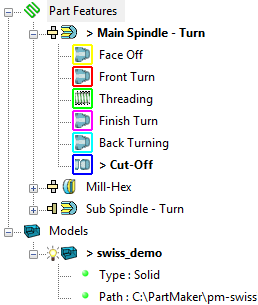
When using a Face window in CAM mode, you can also view the groups of part features that have been programmed in each Face window. For example:
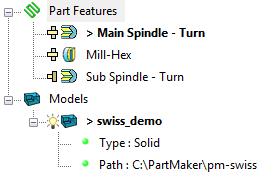
CAD mode:
CAD mode:
Expanding and collapsing items
You can control how much information is displayed in the Job Explorer pane by expanding and collapsing items:
- Click
 to expand an item.
- Click
 to collapse an item.
For example:

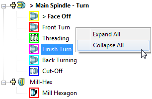
To expand or collapse all items, right-click in a blank area of the Job Explorer pane and select Expand All or Collapse All from the menu:
Identifying the currently selected items
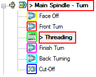
The currently selected items in the Job Explorer pane are displayed in the main PartMaker windows. These items are preceded by the > symbol and shown in bold. For example:
Grouping items
The Face window items are grouped beneath the
Part Features
 item. Any solid, surface, or triangle models are grouped beneath the
Models
item. Any solid, surface, or triangle models are grouped beneath the
Models
 item.
item.
Controlling the visibility of models
To change the visibility of a model, click the light bulb beside the model. If the light bulb is on ( ), the model is visible in the Face window. If the light bulb is off (
 ), the model is not visible in the Face window. Hiding a model to make it easier to view and work on the remaining visible models.
Model information
When expanded, each model item displays the following information:
Type — The type of model. There are three possible types:
- Solid (closed, watertight body)
- Surface (open body)
- Triangulated (.stl file data)
Path — The path of the file from which the model was imported.
Machining function icons
The icon next to each Face window denotes the type of machining function programmed in the Face window. For example, in PartMaker/Mill an XY Plane using Box stock is shown as:

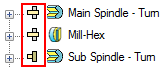
Spindle icons
In PartMaker/SwissCAM and PartMaker/Turn-Mill only, an additional icon denotes whether programming in the Face window is on the main spindle or the sub-spindle. For example:
Group icons
The icon next to a group denotes the type of machining strategy used for that group and the colored border denotes the color used for its profile in the Face window. For example:

Double-clicking a group icon displays the dialog containing the settings for that group, such as the Profile Group Parameters dialog, the Hole Group Parameters dialog or the Surface Group Parameters dialog.
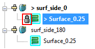
When using surface machining in PartMaker/SwissCAM, PartMaker/Turn-Mill or PartMaker/Mill, an additional lock icon denotes when the group's toolpath is locked. For example:
Menu options
Right-click an item (or its icon) in the Job Explorer pane to display a list of menu options relevant to that item. For example:
- For a Face window:

- For a group:
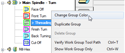
Selecting the Change Group Color option displays the Color dialog, where you can select a new color for the group. PartMaker also uses the color you select to update the sample color in the Color Palette.