
Connectors
Connectors are essential for joining two parts together, and the software allows an unlimited number of connectors to be defined. They play a vital role in every part by specifying how one part connects to the next. Typically, connectors are assigned to the open ends of pipes, fittings, or equipment.
Connector Categorization and Preview
Connectors are categorized into three main types: Rectangular, Round, and Oval. Each type is organized into libraries, which can be further divided into groups of similar connectors. For example, pipework connections are defined within the Round library.
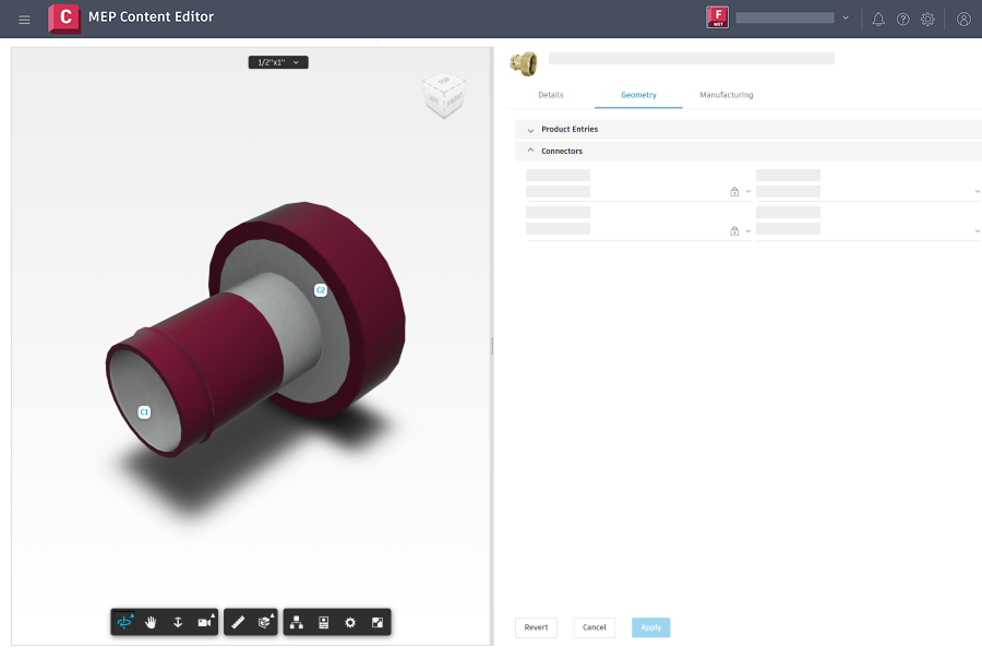
Connectors can be assigned through part specifications or dynamically applied to parts as needed. The connector preview is helpful especially when adding a connector while viewing a part.
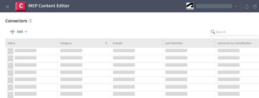
Search for a Connector
In MEP Content Editor, click Components > Connectors.
In the search box, enter a search string to locate a connector.
Click to customize the column display.
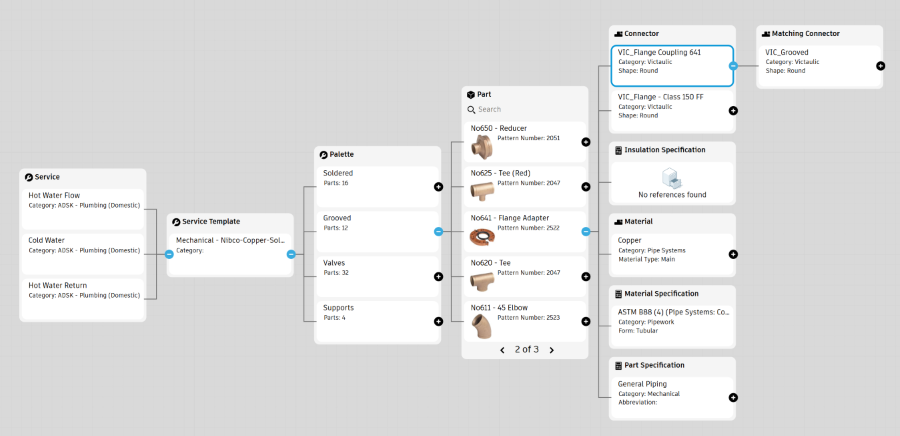
View Relationships for a Connector
Select a connector and click Relationships to investigate all data associated with a connector. See View and Manage Fabrication Data Relationships
Add a Connector
Click Add to add a connector.
Select Round, Rectangular, or Oval.
Specify the following information as needed.
Basic
- Name: The name is combined with the Category field when displayed in the list of connectors in Revit.
- Category: The category is used to organize the list of connectors.
- Shape: The default shape is set to round.
- Gender: The Gender controls which connectors can connect to each other.
- Domain: The Domain controls which connectors appear when placing fabrication parts in Revit.
- Connectivity Classification: The Connectivity Classification is used with the Gender field to control which connectors can connect.
- Matching Connector: Specify a Matching Connector to apply when placing fabrication parts in Revit.
- Pipework End Type: The Pipework End Type is used to support PCF Export in Revit.
- Pressure Class: The Pressure Class field is optional.
Geometry
- Geometry Type: The Geometry Type defines the geometry for the connector.
- Measurement Mode: Select either the outside diameter commonly used for flanges, or the wall thickness.
- The table under Geometry defines the connector breakpoints when placing fabrication parts in Revit.
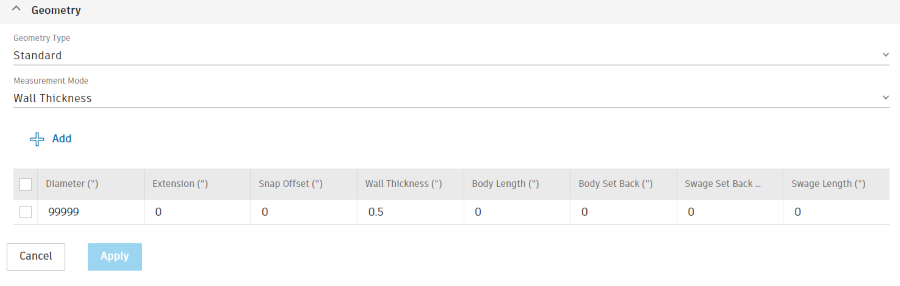
Click Apply. The connector is added to the library.
Duplicate a Connector
You can duplicate an existing connector, then rename and edit it to create a new connector.
Select a connector and click Duplicate.
Delete or Modify a Connector
Select a connector and click Edit or Delete.
Tip: You can double-click a connector to edit it.
Note: If you have Viewer access to the fabrication configuration and select a connector, View appears in place of Edit.