The buildstyle can be found at C:\ProgramData\Autodesk\ATU\ATU-Examples\tutorial-projects\geometry\06_In-Out-Loops\.
For the most part, this buildstyle is identical to the one above (01_2d-Geometry). It creates a model with 10 layers and each layer contains a rectangle.
The new code is added as a new JavaScript file, called geometry.js. For each layer the demonstration function is called. The layer object and the layer index are passed to the new function.
exports.createLayerGeometry = function(layer, layerIdx)
{
exports.createLayerGeometry = function(layer, layerIdx)
{
  var path = new PATH_SET.bsPathSet();
  var points = new Array();

  // counter clock wise (Out-Loop)
  points.push( new VEC2.Vec2(64.90, -3.79));
  points.push( new VEC2.Vec2(62.81,  3.28));
  points.push( new VEC2.Vec2(65.19,  3.90));
  points.push( new VEC2.Vec2(57.81,  4.10));
  points.push( new VEC2.Vec2(57.95,  6.55));
  points.push( new VEC2.Vec2(55.48, -0.39));
  points.push( new VEC2.Vec2(53.19,  0.49));
  points.push( new VEC2.Vec2(59.04, -4.00));
  points.push( new VEC2.Vec2(57.48, -5.89));
  points.push( new VEC2.Vec2(63.57, -1.73));

// clock wise (In-Loop)
//   points.push( new VEC2.Vec2(64.90, -3.79));
//   points.push( new VEC2.Vec2(63.57, -1.73));
//   points.push( new VEC2.Vec2(57.48, -5.89));
//   points.push( new VEC2.Vec2(59.04, -4.00));
//   points.push( new VEC2.Vec2(53.19,  0.49));
//   points.push( new VEC2.Vec2(55.48, -0.39));
//   points.push( new VEC2.Vec2(57.95,  6.55));
//   points.push( new VEC2.Vec2(57.81,  4.10));
//   points.push( new VEC2.Vec2(65.19,  3.90));
//   points.push( new VEC2.Vec2(62.81,  3.28));
//   points.push( new VEC2.Vec2(64.90, -3.79));
  path.addNewPath(points);
  //path.setClosed(true);

  layer.addPathSet(path, MODEL.nSubtypePart);
};
Functional Description (Step by Step)
A path is created with two different point arrays and added to the current layer. The first array contains the points in a clockwise direction the second one in a counterclockwise direction.
Examine Buildstyle Calculation Results
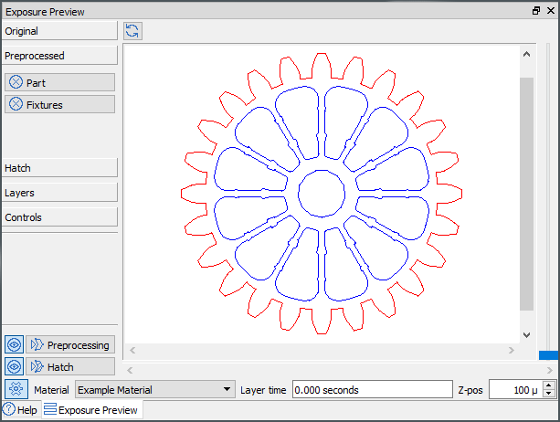
For closed polylines the Advanced Toolpath Utility uses the point direction to differentiate between solid areas and holes. The following example shows a closed area (red) with a few holes inside (blue):
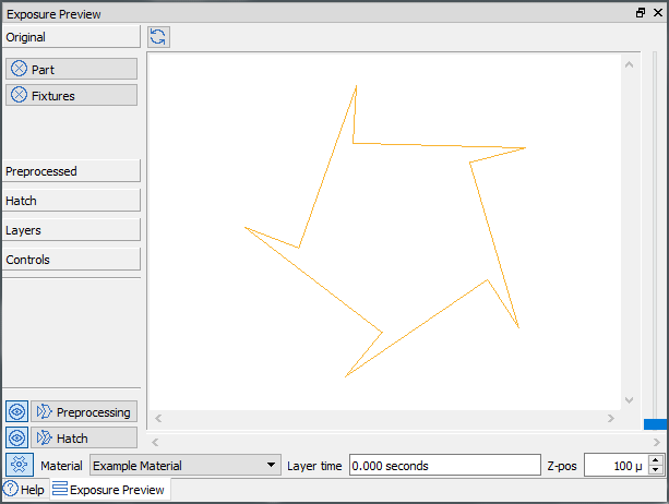
Using the array of clockwise arranged points, the exposure preview widget will be empty, because a hole is constructed without any solid area around it. The counterclockwise oriented point array will show a closed polygon: