
In the , right-click . You will notice that solid elements can only be selected in Assembly context.
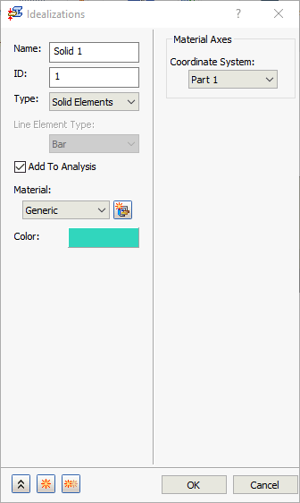
Single Part Context:
Assembly Context:
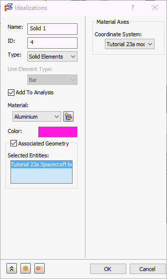
- Associated Geometry: This option is only available for assemblies. The Solid Element type of Idealization is applied on a per-part basis. When the
Associated Geometry option is NOT activated, the Idealization is applied to the entire model (all parts). Activate this option to define unique Idealization properties for individual bodies within the assembly. Select the bodies to which you want to assign the current set of properties, and they appear in the
Selected Entities list.
In the example images that follow, two different materials and colors are assigned to two different parts of an assembly:
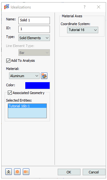
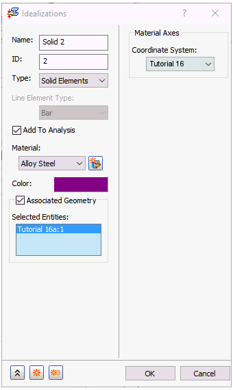
- Material Axes: Assign a material coordinate system for elements with orthogonal material. Global and User-defined Coordinate can be assigned as the material coordinate.
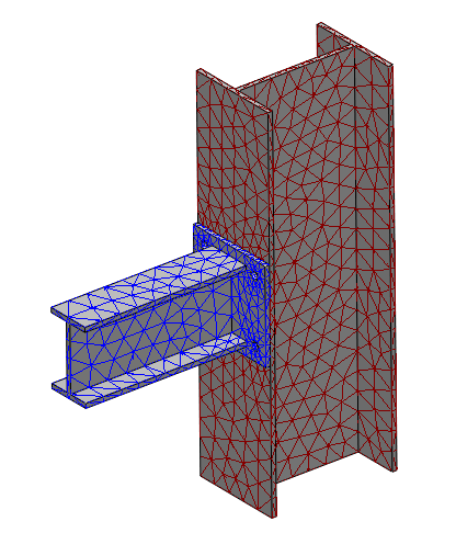
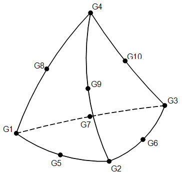
Solid Parabolic Tetrahedral Element Connection:
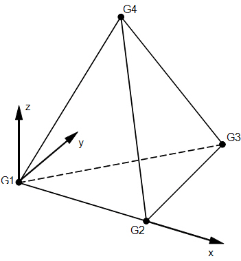
Solid Element Coordinate System:
 It is strongly recommended to use parabolic tetrahedral elements for accurate results. Use linear tetrahedral elements carefully. An example application of linear elements might be to reduce the size of the model in areas where results are not of primary interest or in heat transfer analysis, but not when thermal stress analysis will be carried out.