
Use symbol lists to enforce standard sizes for items such as pipe specs, pipe sizes, and instrument types, or when you want designers to choose from a predefined set of options.
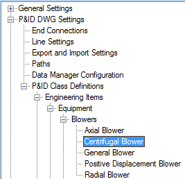
- In the Project Setup tree view, expand P&ID Class Definitions.
- Continue to expand the list until you locate and click a component (for example:
Centrifugal Blower).
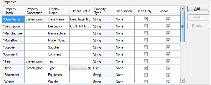
- On the Class Settings pane, under Properties, click Add.
- In the Add Property dialog box, do the following;
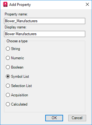
- Click Symbol List.
- Specify a property name for the component or line (for example: Blower_Manufacturers).
- Specify a display name for the component or line (for example: Blower Manufacturers).
- Click OK.
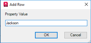
Note: To create a property that uses a symbol list, you assign more than one symbol to the component class definition. - In the Symbol List Property dialog box, click Add Row.
- In the Add Row dialog box, under Property Value, enter the name of the new symbol list entry (for example:
Jackson). Click OK.
- In the Symbol List Property dialog box, under Property Value, click the new entry. Under Block Value, in the drop-down list, click a symbol to assign to the property value.
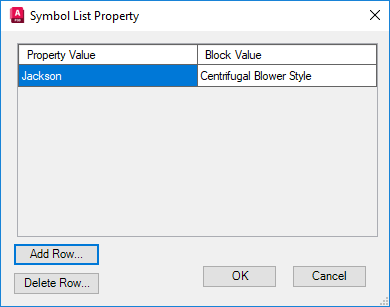
- Continue adding rows until the symbol list is complete.
- Click OK.