
Use selection lists to enforce standard sizes for items such as pipe specs, pipe sizes, and instrument types, or when you want designers to choose from a predefined set of options.
- In the Project Setup tree view, expand Plant 3D DWG Settings.
- Continue to expand the list until you locate and click a Plant 3D object class definition (for example: Piping and Equipment).
- On the Class Settings pane, under Properties, click Add.
- In the Add Property dialog box, do the following;
- Under Type, click Selection List.
- Under Property Name, enter a name for the new property (for example: Pump_Manufacturers). The name cannot contain any spaces.
- Under Display Name, enter the name you want to be displayed for the new property (for example: Pump Manufacturers) in the Data Manager or Properties palette.
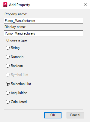
- Click OK.
- In the Selection List Property dialog box, click Add List.
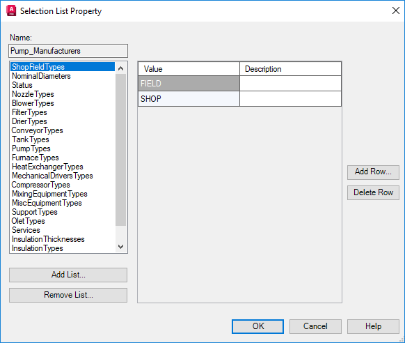
- In the Add Selection List dialog box, enter the name for the new selection list (for example: Manufacturers). Click OK.
- In the Selection List Property dialog box, click Add Row.
- In the Add Row dialog box, enter the new value (for example:
Goulds) and a description of the value, if necessary.
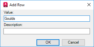
- Continue adding rows until the selection list is complete.
- Click OK.
On the Class Settings pane, under Properties, the selection list is displayed for the selected class definition. The value displayed in the list is the default value for that Plant 3D object.