Use the Tools tab > Transform panel > Mirror Wizard option to create a mirror image of the current inspection through a specified axis in a specified plane.
To mirror the current inspection:
- Click Tools tab > Transform panel > Mirror Wizard. The Results output setup page is displayed.
- Choose an output option. Select:
- Modify the active document to overwrite the current document with the mirrored inspection.
- Create a new document to create a mirror inspection in a new file. Enter the location and name of the document in the box.
- Click
Next. The
Mirror plane setup page is displayed.
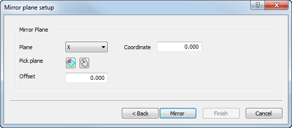
- In the
Mirror
Plane area, select the plane in which you want to mirror the part. To mirror the part in a:
- major plane, select X, Y, or Z in the Plane list, and type the position of the mirror plane in the Coordinate box.
- custom plane, click
 . In the CAD view, click and drag the cursor across the model. The coordinates of the point that defines the mirror plane and the normal vector of the reference plane are displayed. Alternatively, select
<Custom> in the
Plane list, and enter the coordinates of the
Point that defines the mirror plane, and the
Vector of the reference plane.
. In the CAD view, click and drag the cursor across the model. The coordinates of the point that defines the mirror plane and the normal vector of the reference plane are displayed. Alternatively, select
<Custom> in the
Plane list, and enter the coordinates of the
Point that defines the mirror plane, and the
Vector of the reference plane.
- selected plane, display the plane you want to use in the CAD view, and click
 . In the CAD view, move the cursor over the model and click the plane.
If you select a plane that parallels a major plane, the major plane and Coordinate of the mirror plane are displayed; if you select non-parallel plane, <Custom> is selected in the Plane list, and the coordinates of the point that defines the mirror plane and the normal vector of the reference plane are displayed.
- To offset the model after mirroring the inspection, enter the Offset distance from the mirroring plane. When you mirror the inspection in a major plane, the offset is applied in the plane's positive direction. When you mirror the inspection in a custom plane, the offset is applied in the direction of the plane's normal vector.
- Click
Mirror.
PowerInspect creates a mirror image of the CAD and the inspection sequence. The
Report dialog displays the results of the mirroring process.
 Note: If the inspection contains a Collision Free Link Path item and Automatic Collision Avoidance Mode is enabled, PowerInspect deletes the item and its probe path. It then creates a new item and new probe path after all other items in the inspection have been mirrored.
 - To view the results in a text file, click
 to select an editor, then click the
Open in editor button.
to select an editor, then click the
Open in editor button.
- To display the text file when you click Finish, select the Automatically open when finish check box.
- Click Finish to close the dialog and use the mirrored inspection.
Examples
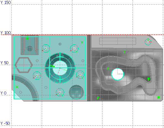
These examples demonstrate the effect of mirroring the following model:
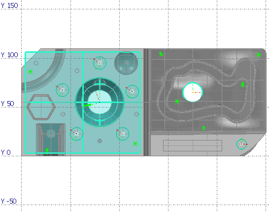
Example 1: Mirroring through the Y=0 axis in the Y plane:

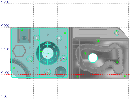
Example 2: Mirroring through the Y=100 axis in the Y plane
Example 3: Mirroring through the Y=100 axis in the Y plane, with offset = 100