
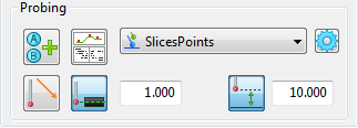
Use the Probing area of the Inspect dialog to specify the probe path used to measure a feature.
Probing strategies and methods
Probing methods are grouped by strategy. The probing strategy determines how a probe path is generated and the probing method determines the shape of the path used to probe the item. Choose a probing method from the following strategies:
 AutoTouchTrigger — Generates the surface and intermediate points required to measure the item. This is the default strategy for geometric features, such as arcs, cones, cylinders, and spheres, and can be selected for inspection groups.
 UserDefined — Specifies the probe path manually using the Probe Path Editor. This is the only strategy available for planes; it can be selected for other geometric features or inspection groups.
 CollisionAvoidance — Generates a collision-free intermediate probe path between features on the part.
 AutoScan — Creates scanning probe paths for a feature.
 UserScan — Specifies the scanning probe path used to measure the selected feature.
In addition, PowerInspect can select the AutoDefined probing method of Fallback when the item's original method is incompatible with the current probe or is unavailable in this version of PowerInspect. Because this method may produce a sub-optimal probe path, you should change it before measuring the part.
To view or change the parameters that control how the probe path is calculated, click the Parameters  button.
Probe orientation
If you are using an indexable probe head, specify the angle from which the feature is probed:
 New Angles — Click this button to manually specify the probe orientation for the feature.
 Enable/Disable Automatic Orientation — Select this button to automatically select the best orientation for probing the feature. For example, when probing a plane, the orientation is the same as the plane's normal vector; when probing a cone, the orientation is the same as the cone's axis.
To view the effect of the probe orientation, use the Simulate Program tab.
Probe path details
Click the Details  button to open Probe Path Details dialog and display the details of the probe path. The information displayed includes approach, search and retract distances and the XYZ, IJK values of each move.
Probe depth
The default depth at which a feature is probed is calculated from the diameter of the probe and the component thickness. To change the depth, click the Probe Depth  button.
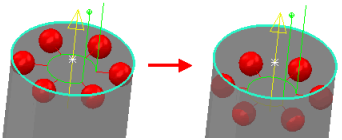
The effects of your changes are displayed in the CAD view. For example, changing the probe depth of an arc from 1 mm to 3 mm lowers the points in 2D features
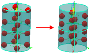
Changing the probe depth of a cone or cylinder changes the depth for both the top and bottom points. This example demonstrates the effect of changing the probe depth from 1 mm to 3 mm for a cylinder:
Safe height
Select the Safe Height  button to specify the safe height to be used when measuring the feature.
This example demonstrates the effect of changing the safe height from 1 mm to 5 mm:
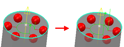
This determines the approach position before the first probed position and the retract position after the last probed position.
The value you enter is taken from the top of the feature. This setting can be useful if the probe has to clear an obstacle to be able to measure the feature. For intermediate probe paths, the Safe height value determines the intermediate safe distance to be applied to when you add intermediate positions to the intermediate path.