
Use the options on the Leads and links tab to specify the properties of the leads and links for a turning toolpath.
The options on the dialog depend on the type of turning toolpath that is active:
Roughing strategies
- Minimum clearance — Specifies the distance of a point away from the beginning of the toolpath that the tool rapidly moves to at the beginning of an operation
The location of this point is also controlled by the Lead out angle and Lead out distance.
- Engage Angle — Enter an angle in degrees, away from the horizontal plane, that the tool moves into the part. This option is available only if you specify a Style of Round Insert.
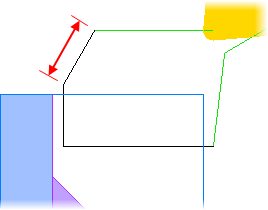
- Lead out angle — Enter the angle that the tool withdraws along before returning for the next step. The angle is measured in degrees, counter-clockwise from the Z axis.
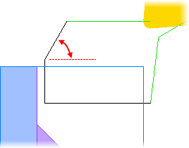
- Lead out distance — Enter the distance along the Withdraw angle line that the tool withdraws before returning for the next step.
- Link clearance — Specifies the minimum distance away from the stock that is safe to use rapid link moves.
Finishing strategies
Lead in — Select the type of lead in.
Arc — Use an arc ramp-in move specified by the Arc angle and Arc radius.
Linear — Use a linear lead-in move specified by the Angle and Length.
- Arc angle — Specify the angle in degrees traversed by the arc lead in move, measured counter-clockwise in the X-Z plane. An angle of 90 starts the approach perpendicular to the path and ends the approach parallel to the path.
- Arc radius — Specify the radius of the arc lead in. This controls its length. These options are available only for a Lead in of Arc.
- Angle — Specify the angle in degrees at which the tool enters the stock, measured counter-clockwise in the X-Z plane. An angle of
0 approaches along the path. An angle of
90 approaches perpendicular to the path.
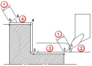
 Clearance
 Lead in angle
 Clearance zone
 Lead out angle
- Length — Specify the distance of the linear lead in. These options are available only for a Lead in of Linear.
- Linear Extension — Click to add a straight lead in prior to existing lead ins. This is useful if you need to apply cutter compensation as it can only operate on linear moves.
- Length — Enter the length of the lead in extension move.
Lead out — Select the type of lead out.
Arc — Use an arc ramp-out move specified by the Arc angle and Arc radius.
Linear — Use a linear lead-out move specified by the Angle and Length.
- Arc angle — Specify the angle in degrees traversed by the arc lead out move, measured counter-clockwise in the X-Z plane. An angle of 90 starts the retract parallel to the path and ends the retract perpendicular to the path.
- Arc radius — Specify the radius of the arc lead out. This controls its length. These options are available only for a Lead out of Arc.
- Angle — Specify the angle in degrees at which the tool retracts from the stock, measured counter-clockwise in the X-Z plane. An angle of 0 retracts along the path. An angle of 90 retracts perpendicular to the path. See Lead in Angle diagram.
- Length — Specify the distance of the linear lead out. These options are available only for a Lead out of Linear.
- Linear Extension — Click to add a straight lead out after existing lead outs. This is useful if you need to apply cutter compensation as it can only operate on linear moves.
- Length — Enter the length of the lead out extension move.
 — Click to copy the
Lead in values to the
Lead out values.
— Click to copy the
Lead in values to the
Lead out values.
 — Click to copy the
Lead out values to the
Lead in values.
— Click to copy the
Lead out values to the
Lead in values.
Clearance — Specifies the minimum distance away from the stock that is safe to use rapid link moves.