
Use the options on the Moves and clearances tab of the Toolpath connections dialog to define the parameters of movement and clearance of the tool through rapid links.
This tab contains the following settings:
Other options
Retract and Approach Moves
Use the options to define the initial retract and final approach moves within rapid links.
Along — Select the orientation of the links.
- Tool axis — The retract and approach moves have the same orientation as the tool axis.
- Contact normal — The retract and approach moves are normal to the contact point (or normal to the
Leads In/Out). This can be useful for tipped disc cutters, where moving along the tool axis may not be possible (for example, when undercutting).
To use this option contact normals must be stored with the toolpath.
- Tangent — The retract and approach moves are tangential to the toolpath.
The retract and approach moves are tangential to the toolpath.
- Radial — The retract and approach moves are perpendicular to both the tool axis and the tangent direction of the toolpath.
To use this option contact normals must be stored with the toolpath.

Minimum retract distance — Enter the minimum length of the initial retract move. The move is automatically extended to avoid gouges and collisions if necessary.
Minimum approach distance — Enter the minimum length of the final approach move. The move is automatically extended to avoid gouges and collisions if necessary.
Automatically extend — Select to extend the retract and approach moves along the specified direction to reach the safe area. This defines the entire retract path to the safe area and the entire approach path from the safe area to be unidirectional.
- Maximum length — Enter the maximum length of the automatic extension. Use this option to limit the extension in cases where a move in the specified direction will reach the safe area, but only after an excessive distance. For example, when a tool axis lies close to the X axis, and the safe area is a plane normal to the Z axis.
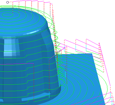
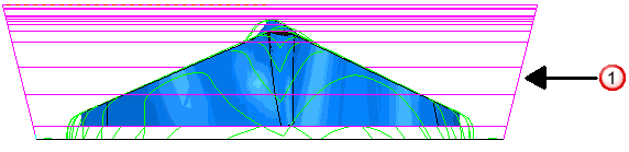
This toolpath has Retract and Approach Moves set to 0:
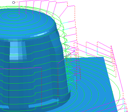
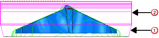
This toolpath has Automatically extend selected:
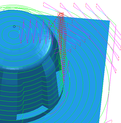
This toolpath has Automatically extend deselected and a Retract and Approach distance of 10:
 Retract along tool axis.
 Retract normal to the safe plane.
Incremental plunge distance
Use the options to define the length and measurement reference of the plunge distance used in skim and incremental links.
Distance — Enter the distance above the start of a toolpath segment to stop a rapid plunge and to start a controlled approach to the toolpath.
Measured from — Select how to measure the specified distance.
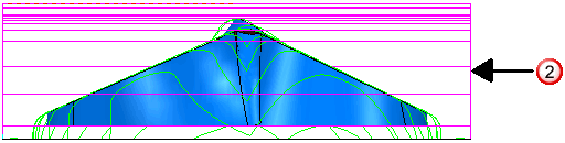
- Previous Z Height — Measures the incremental distances for plunge-moves and ramps leads relative to the Z Height that lies above the start of the toolpath segment (previous Z height). A Distance
of
2
gives:
This option is available only for area clearance toolpaths.
- Toolpath Point — Measures the incremental distances for plunge-moves and ramp leads relative to the start of the toolpath segment (current Z height). A Distance
of
2
gives:
Planar skim moves
Use the options to define the position and orientation of the plane used for skim links.
Use with a non-planar safe area — Select this option to use a planar skim surface. This option is only available for toolpaths with spherical or cylindrical safe areas.
Plane — Select an option from the list to define the orientation of the skim plane:
- Automatic — The skim plane is normal to the Z direction of the toolpath.
- Interpolated — The skim plane is normal to the vector halfway between the directions of the retract move and the reverse of the approach direction.
- Safe area — The skim plane is parallel to the safe area. This option is only available for toolpaths with a planar safe area.
- Workplane Z — The skim plane is normal to the Z direction of an existing workplane, selected from the Workplane field.
Workplane — Select a workplane to orientate the skim plane from. This option is available only if you select a Plane of Workplane Z.
Arc Fit Rapid Moves
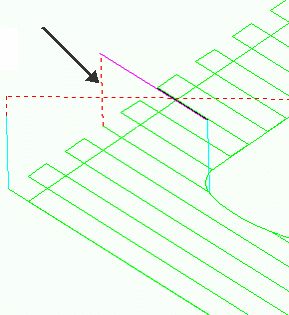
When the option is deselected, rapid moves are linear and form right-angles with the link moves:
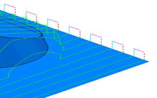
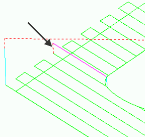
When the option is selected, rapid moves are curved and form arcs with the link moves. The arc radius is controlled by the Arc Radius (TDU) field:
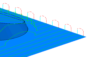
Use the options to place arcs on the corners of link moves as the tool rapids across the part. This avoids sudden changes in direction and is useful when high speed machining.
Arc radius (tool diameter units) — Enter the radius of the arc used to replace the corners.
Clearances
Use the options to define the clearances used when defining skim links and when adjusting approach and retract moves to avoid gouges..
Axial clearance — Enter a clearance required along the tool axis.
Radial clearance — Enter a clearance required in the tool's radial direction.
Other options
Gouge check — Select this option for PowerMill to gouge-check all leads and links.
Apply rapid moves — Click to save your changes and recalculate the first approach, final retract and all links that have rapid moves with respect to the safe area and the new rapid move settings.
Apply — Click to apply the values to the currently active toolpath.
Accept — Click to accept the values on this dialog and closes the dialog.
Cancel — Click to close the dialog without updating the leads and links.