
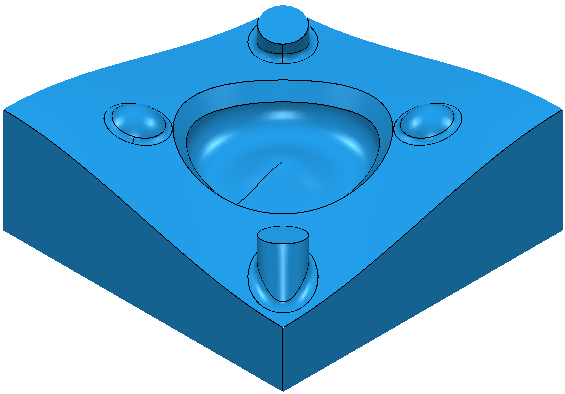
This example uses the 5_axis_Test.dgk model in the Examples folder.
- Create a
Block
and define a 10 mm ball nosed
Tool.
Ensure the block extends above the top of the model.
- Select the top surface.
- From the
Boundaries context menu, select
Create Boundary > Contact Point. This displays the
Contact Point dialog.
- Click the
Model
 button.
- Select the Allow boundary to be private option.
- Click Accept.
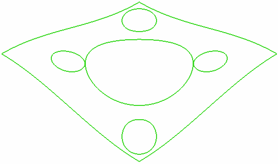
For more information, see Example of Contact Point Boundary.
The boundary appears in the Boundaries branch of the Explorer.
- Click the
Model
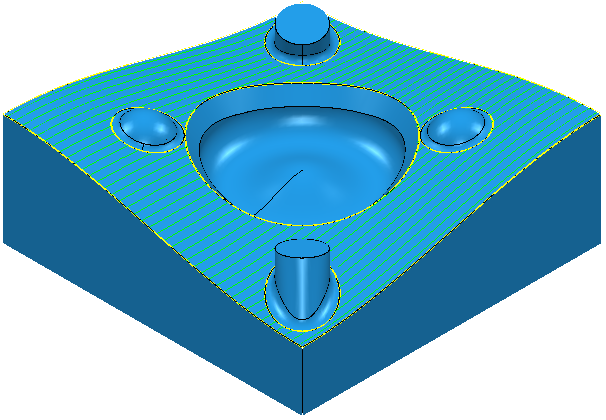
- Create a
Raster Finishing toolpath using the
Contact Point Boundary.
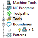
The boundary is no longer displayed in the Boundaries branch of the Explorer. Instead, it is displayed in the individual toolpath branch of the Explorer.
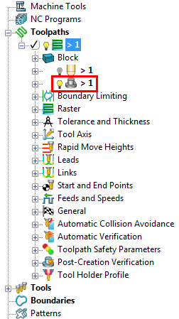
The icon changes from
 to
to
 .
.
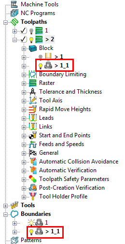
- Click File tab > Options > Application Options > Boundaries > Private boundaries and select
Display private boundaries in the explorer to display this boundary in the
Boundaries branch of the Explorer.

- If you try to create another toolpath which uses this private boundary, the new toolpath creates a copy of the private boundary.
- If you delete a toolpath which uses a private boundary, the private boundary is deleted along with the toolpath.