
The options for the Mode list depend on your choice of Tool axis.
Lead/Lean
With a Tool Axis of Lead/Lean, the Lead angle is measured relative to the reference direction in the direction of travel. The Lean angle is measured relative to the plane containing the reference direction and the tool movement direction. So, with a Lead of 0 and a Lean of 0, the tool is aligned with the reference direction.
For this tool axis definition, the options in the Mode list are:
- Contact normal — This measures the lead angle from the toolpath contact normal. This is the default option.
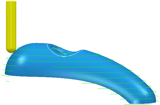
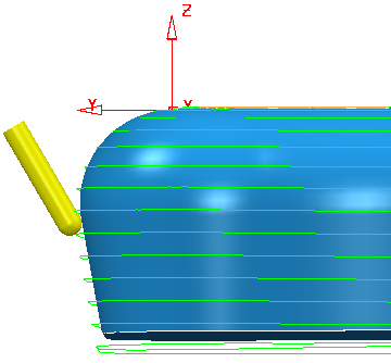
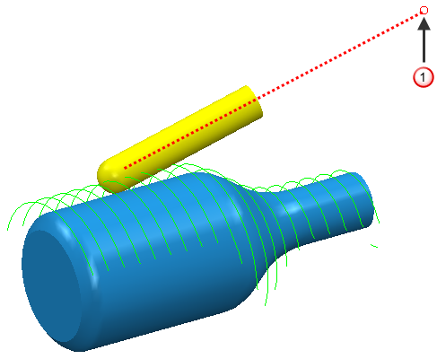
This example uses a constant Z toolpath with a Tool axis of:
Lead angle of 0

Lean angle of 0
Mode of Contact normal.

- Vertical — This measures the lead angle from the Z axis.
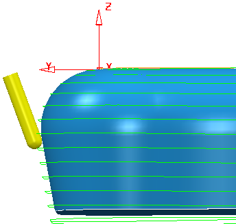
This example uses a constant Z toolpath with a Tool axis of:
Lead angle of 0
Lean angle of 0
Mode of Vertical.
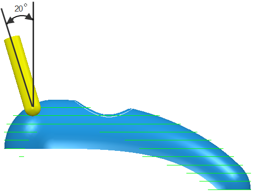
This example uses a constant Z toolpath with a Tool axis of:
Lead angle of 20
Lean angle of 0
Mode of Vertical.
- PowerMILL 2012 R2 — The behaviour available in PowerMill 2012R2 which, in most cases, used a Mode of Vertical.
The strategies which used a Mode other than Vertical are:
|
Strategy |
PowerMILL 2012 R2 mode |
|
Embedded pattern |
Contact normal |
|
Flowline |
Contact normal |
|
Parametric spiral |
Undercut angle |
|
Pattern, using toolpath |
Reference tool axis |
|
Profile |
Contact normal |
|
Projection (curve, line, plane, point, surface) |
Preview frame normal |
|
Surface machining |
Contact normal |
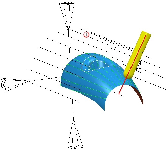
- Preview frame normal — This measures the lead angle from the normal to the pattern that forms the preview frame.
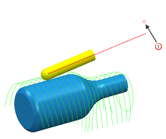
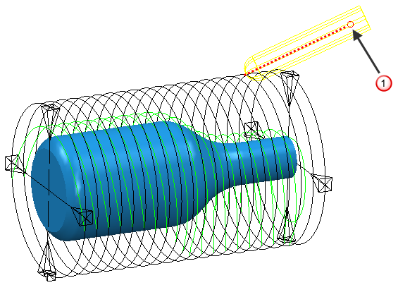
This example uses a line projection toolpath with a Tool axis of:
Lead angle of 0
Lean angle of 0
Mode of Preview frame normal.
 Preview frame
The tool is normal to the pattern (or preview frame).
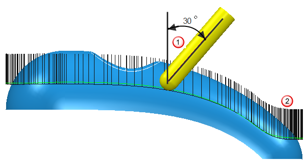
- Reference tool axis — This measures the lead angle from the tool axis used by the reference toolpath. This option is available only for pattern finishing toolpaths which use a toolpath as the drive curve.
This example uses a pattern toolpath which uses a reference toolpath as the drive curve, and a Tool axis of:
Lead angle of 30
Lean angle of 0
Mode of Reference tool axis.
 Lead angle
 Tool axis of reference toolpath
 - Tangent normal — This measures the lead angle from the perpendicular to the tangent direction of the reference curve. This option is available only for pattern finishing toolpaths which use a pattern as the drive curve.
This example uses a pattern toolpath with a Tool axis of:
Lead angle of 0
Lean angle of 0
Mode of Tangent normal.

- Undercut angle — This measures the lead angle from the projection direction corresponding to the specified degree of undercut. This option is available only for parametric spiral toolpaths.
This example uses a parametric spiral toolpath with an Undercut Angle of 10
and a Tool axis of:Tool Axis of Lead/Lean
Lead angle of 0
Lean angle of -20
Mode of Undercut Angle.
With the same options except:
Mode of Vertical.
Tool Axis of Towards... or From...
With a Tool Axis of Towards... or From... the Mode options are:
- Preview frame — The tool axis is defined on the preview frame and then the toolpath is projected onto the model.
A Tool axis of From point
A Mode of Preview Frame
 the From point
The tool axis does not pass through the From point. However, if you offset the tool to the preview frame it would pass through the From point.
- Toolpath — The toolpath is projected onto the model and then the tool axis is defined on the model.
A Tool axis of From point
A Mode of Toolpath
 The tool axis passes through the From point.