
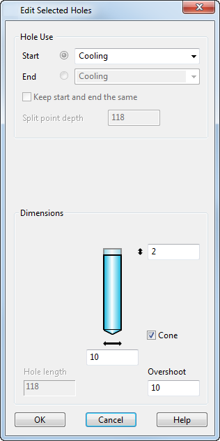
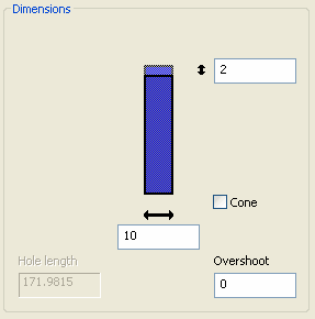
This dialog defines the type of holes which are used by a cooling channel:
If you are editing multiple holes, the values on the dialog are for one of the holes in the selection list. If you specify an invalid value for a particular hole, that hole is not updated but the others are.
Hole Use:
- Select the type of hole used in the cooling channel from the drop-down list. If the cooling channel is a through hole, you define the start and end holes by selecting
Start and
End options:
- Start — Specifies the type of hole for the start hole. Select the type of hole. The dimensions for the hole are displayed.
If the cooling channel is not a through hole, the Start option defines the hole.
To set the dimensions for the start hole, make sure the toggle button on the left is selected. The dimensions for the hole are displayed.
- End — (Only available for through holes) This specifies the type of hole for the end of the through hole. Select the type of hole. The dimensions for the hole are displayed.
To set the dimensions for the end hole, select the toggle button on the left. The dimensions for the hole are displayed.
The Cooling Wizard uses all available, appropriate solid hole types, allowing you to define drill, tapping, tapping pre-drill and counterbore diameters and depths.
- Start — Specifies the type of hole for the start hole. Select the type of hole. The dimensions for the hole are displayed.
- Keep start and end the same — (Only available for through holes) If this option is selected and you change a dimension of any hole, the equivalent dimension of the other hole changes too.
If this option is deselected, the changes only apply to the end that is currently selected.
- Split point depth — (Only available for through holes) This is the position along the start hole where the end hole joins it.
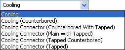
Dimensions:
- For each hole type, an image of a hole is given with boxes to change particular dimensions.
For each type of hole, you can set different dimensions. The explanation is similar for each hole:
If you want to set the dimensions for the start hole, select the toggle next to Start. Similarly, if you want to set the dimensions for the end hole, select the toggle next to End.
You can change the size of the hole by entering values in the dimension boxes. For tapped holes, you can also change the sizes by selecting different Standard and Size options.
The safety margin is the length above the hole which ensures that the hole cuts the mold plate correctly when drilled:
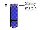
The safety margin is added to the start of each hole automatically. If the hole cuts straight through the mold plate, the safety margin is also added to the end of the hole.
- Cone — This adds a cone to the tip of the hole.
- Hole length — This is the length of the hole. You cannot edit this length here. To change it, you must change the length of the layout piece line.
- Overshoot — Holes are extended by this length to ensure they intersect with each other within the mold plates. This value is not added to holes that cut straight through a mold plate.
Tapping details:
Use this area to set the tapping details of the hole. You can set the standard and size of the hole using these options.
- Standard — Select the name of the standard. If you want enter your own values, select User defined.
- Size — Select the size.
- Tapping Depth — Input a depth value.
- Tapping Diameter — Input a diameter value.
- Tapping pre-drill diameter — Input a pre-drill diameter.
- Tap Pitch — (Only available for User defined tapping) Input a pitch value.
OK — Accepts the changes to the hole and closes the dialog.